Weider Club C 725 English Manual - Page 18
Attach the Left Arm 22 to the Arm Frame 24
 |
View all Weider Club C 725 manuals
Add to My Manuals
Save this manual to your list of manuals |
Page 18 highlights
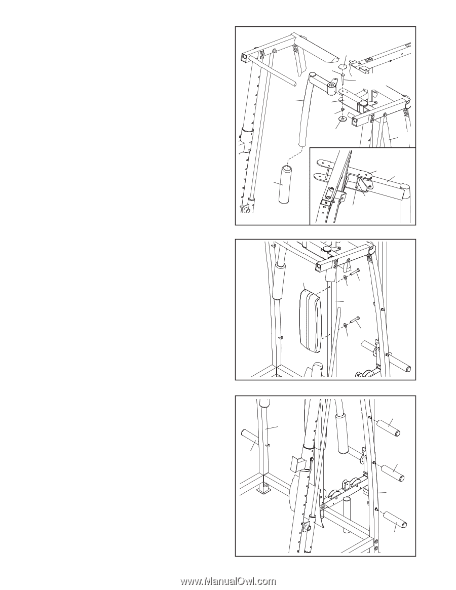
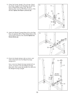
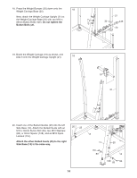
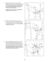
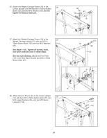
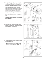
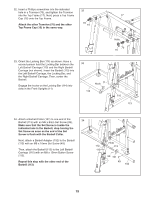
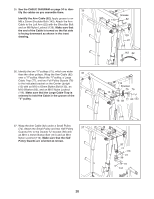
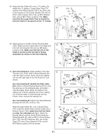
29. Identify the Right Arm (23) and insert it into the Arm Frame (24). See the inset drawing. Make sure that the welded pin on the Right Arm is behind the rod on the Arm Frame as shown. Apply grease to an M10 x 94mm Bolt (134). Attach the Right Arm (23) to the Arm Frame (24) with the Bolt and an M10 Thin Nylon Locknut (86). Do not overtighten the Thin Nylon Locknut; the Right Arm must pivot easily. Next, press two Bushing Caps (88) onto the Bolt and the Thin Nylon Locknut. Next, slide an Arm Pad (89) onto the Right Arm (23). Attach the Left Arm (22) to the Arm Frame (24) in the same way. 29 23 89 88 134 Grease 24 86 88 22 View from back 24 23 Pin Rod 30. Attach the Center Backrest (69) to the Center 30 Upright (13) with two M6 x 65mm Button Screws (126) and two M6 Washers (142). 69 126 142 13 126 142 31. Tighten three Weight Storage Tubes (67) onto the 31 Left Rear Upright (12). Tighten the remaining three Weight Storage 60 Tubes (67) onto the Right Rear Upright (60). 67 18 67 67 12 67
-
 1
1 -
2
-
3
-
4
-
5
-
6
-
7
-
8
-
9
-
10
-
11
-
12
-
 13
13 -
 14
14 -
 15
15 -
 16
16 -
 17
17 -
 18
18 -
 19
19 -
 20
20 -
 21
21 -
 22
22 -
 23
23 -
24
-
25
-
26
-
27
-
28
-
29
-
30
-
31
-
32
-
33
-
34
-
35
-
36
-
37
-
38
-
39
-
40
-
41
-
42
-
43
-
44
 |
 |