Weider Club C 725 English Manual - Page 25
Bolt and the Small Pulley 74.
 |
View all Weider Club C 725 manuals
Add to My Manuals
Save this manual to your list of manuals |
Page 25 highlights
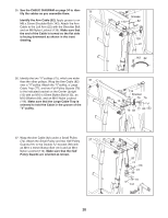
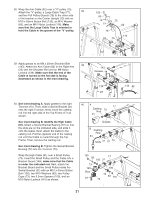
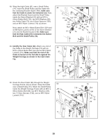
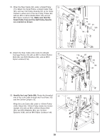
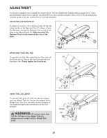
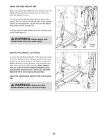
48. Wrap the High Cable (81) over a Small Pulley (74). Insert the Small Pulley and the Cable into the remaining Bracket Guard (149); make sure that the Cable is under the indicated rod. Next, attach the Bracket Guard and the Small Pulley inside the Swivel Bracket (31) with an M10 x 60mm Button Bolt (136), two M10 Washers (83), two Pulley Caps (73), two 6.5mm Spacers (100), and an M10 Nylon Locknut (116) as shown. Next, attach an M6 x 48mm Button Bolt (124) and an M6 Nylon Locknut (150) to the Swivel Bracket (31) and the Bracket Guard (149). Make sure that the High Cable (81) is between the Button Bolt and the Small Pulley (74). 48 116 100 150 83 73 149 124 Rod 81 31 100 73 74 83 136 49. Identify the Rear Cable (94). Attach one end of the Cable to the Weight Carriage (19) with an 49 M10 x 20mm Button Bolt (56) and an M10 Nylon Locknut (116). Make sure that the end of the Cable is turned so the flat side is against the Weight Carriage as shown in the inset draw- ing. 50. Route the Rear Cable (94) through the Weight Carriage Frame (18) as shown. Wrap the Cable over a Small Pulley (74). Attach the Small Pulley inside the Weight Carriage Frame with an M10 x 65mm Button Bolt (66), two M10 Washers (83), two 12.5mm Spacers (138), and an M10 Nylon Locknut (116). 94 56 19 50 116 94 116 56 19 83 116 18 138 74 Slot 138 83 66 94 25
-
 1
1 -
2
-
3
-
4
-
5
-
6
-
7
-
8
-
9
-
10
-
11
-
12
-
13
-
14
-
15
-
16
-
17
-
18
-
19
-
 20
20 -
 21
21 -
 22
22 -
 23
23 -
 24
24 -
 25
25 -
 26
26 -
 27
27 -
 28
28 -
 29
29 -
 30
30 -
31
-
32
-
33
-
34
-
35
-
36
-
37
-
38
-
39
-
40
-
41
-
42
-
43
-
44
 |
 |
