Weider Club C 725 English Manual - Page 20
Identify the Arm Cable 82.
 |
View all Weider Club C 725 manuals
Add to My Manuals
Save this manual to your list of manuals |
Page 20 highlights
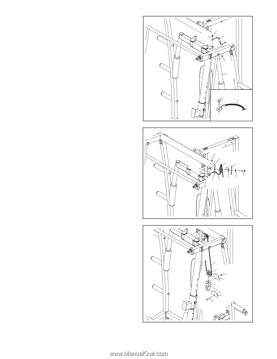
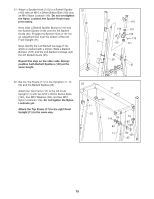
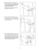
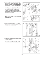
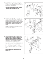
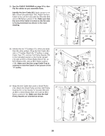
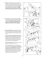
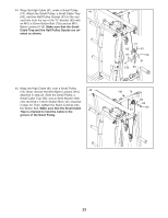
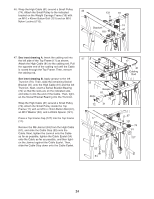
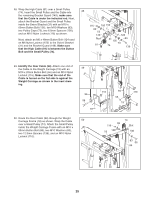
35. See the CABLE DIAGRAM on page 34 to iden- 35 tify the cables as you assemble them. Identify the Arm Cable (82). Apply grease to an M8 x 25mm Shoulder Bolt (143). Attach the Arm Cable to the Left Arm (22) with the Shoulder Bolt and an M8 Nylon Locknut (139). Make sure that the end of the Cable is turned so the flat side is facing downward as shown in the inset drawing. 36. Identify the two "V"-pulleys (75), which are wider than the other pulleys. Wrap the Arm Cable (82) 36 over a "V"-pulley. Attach the "V"-pulley, a Large Cable Trap (77), and two Full Pulley Guards (76) to the indicated bracket on the Center Upright (13) with an M10 x 63mm Button Bolt (133), an M10 Washer (83), and an M10 Nylon Locknut (116). Make sure that the Large Cable Trap is oriented to hold the Cable in the groove of the "V"-pulley. Grease 143 82 139 22 143 82 116 Bracket 75 76 13 76 82 77 83 133 37. Wrap the Arm Cable (82) under a Small Pulley (74). Attach the Small Pulley and two Half Pulley 37 Guards (91) to the Double "U"-bracket (98) with an M10 x 45mm Button Bolt (131) and an M10 Nylon Locknut (116). Make sure that the Half Pulley Guards are oriented as shown. 20 82 74 116 91 98 91 131
-
 1
1 -
2
-
3
-
4
-
5
-
6
-
7
-
8
-
9
-
10
-
11
-
12
-
13
-
14
-
 15
15 -
 16
16 -
 17
17 -
 18
18 -
 19
19 -
 20
20 -
 21
21 -
 22
22 -
 23
23 -
 24
24 -
 25
25 -
26
-
27
-
28
-
29
-
30
-
31
-
32
-
33
-
34
-
35
-
36
-
37
-
38
-
39
-
40
-
41
-
42
-
43
-
44
 |
 |