Weider Club C 725 English Manual - Page 24
See inset drawing A., See inset drawing B.
 |
View all Weider Club C 725 manuals
Add to My Manuals
Save this manual to your list of manuals |
Page 24 highlights
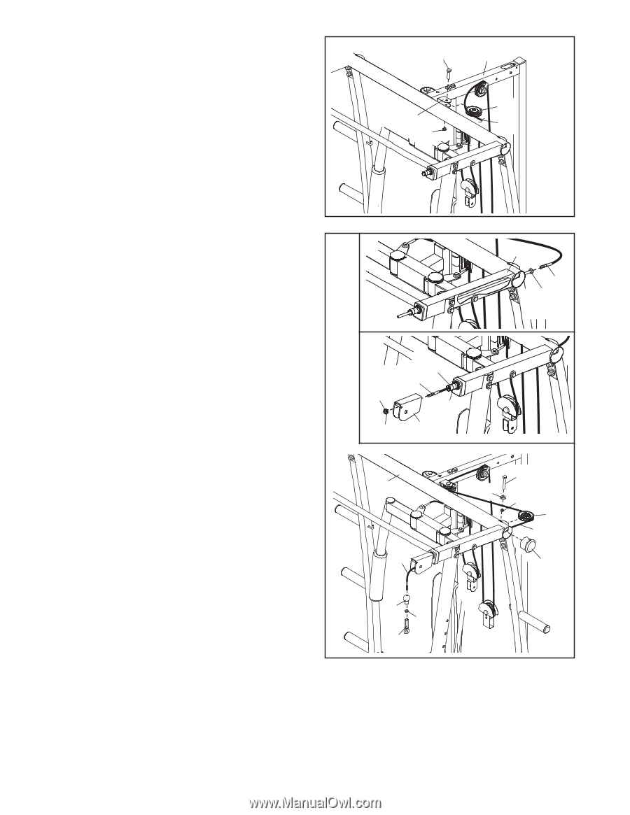
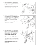
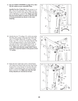
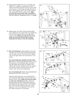
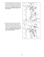
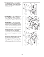
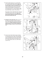
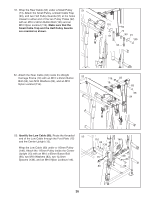
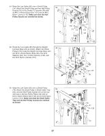
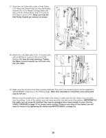
46. Wrap the High Cable (81) around a Small Pulley (74). Attach the Small Pulley to the indicated 46 bracket on the Weight Carriage Frame (18) with an M10 x 45mm Button Bolt (131) and an M10 Nylon Locknut (116). 131 18 74 Bracket 81 116 47. See inset drawing A. Insert the cabling rod into the left side of the Top Frame (17) as shown. Attach the High Cable (81) to the cabling rod. Pull the opposite end of the cabling rod until the Cable is routed through the Top Frame. Then, remove the cabling rod. See inset drawing B. Apply grease to the left Trunnion (70). Then, slide the remaining Swivel Bracket (31) onto the High Cable (81) and the left Trunnion. Next, orient a Swivel Bracket Bearing (72) so that the slots are on the indicated side, and slide it onto the end of the Cable. Then, tighten the Swivel Bracket Bearing into the Trunnion. Wrap the High Cable (81) around a Small Pulley (74). Attach the Small Pulley inside the Top Frame (17) with an M10 x 70mm Button Bolt (97), an M10 Washer (83), and a 25mm Spacer (121). Press a Top Frame Cap (127) into the Top Frame (17). Remove the M8 Jamnut (53) from the High Cable (81), and slide the Cable Stop (55) onto the Cable. Next, tighten the Jamnut onto the Cable as far as possible, tighten the Cable Eyelet (54) onto the Cable as far as possible, and then tighten the Jamnut against the Cable Eyelet. Then, slide the Cable Stop down onto the Cable Eyelet. 47 A B Slots 72 Grease 81 70 31 17 81 55 53 54 17 81 Cabling Rod 97 83 121 74 81 127 24
-
 1
1 -
2
-
3
-
4
-
5
-
6
-
7
-
8
-
9
-
10
-
11
-
12
-
13
-
14
-
15
-
16
-
17
-
18
-
 19
19 -
 20
20 -
 21
21 -
 22
22 -
 23
23 -
 24
24 -
 25
25 -
 26
26 -
 27
27 -
 28
28 -
 29
29 -
30
-
31
-
32
-
33
-
34
-
35
-
36
-
37
-
38
-
39
-
40
-
41
-
42
-
43
-
44
 |
 |