Weider Pro 9645 English Manual - Page 11
Weider Pro 9645 Manual
 |
View all Weider Pro 9645 manuals
Add to My Manuals
Save this manual to your list of manuals |
Page 11 highlights
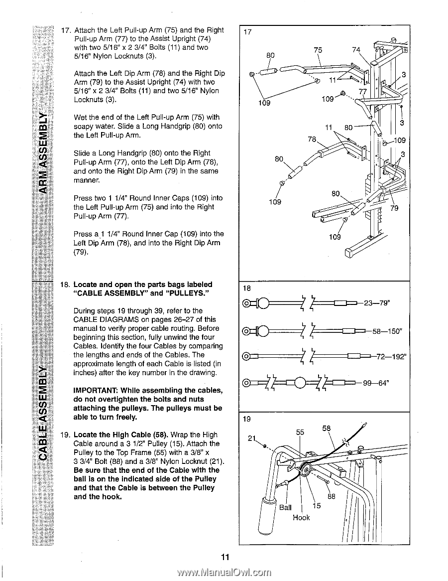
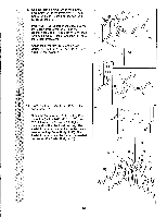
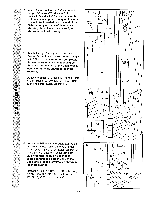
17. Attach the Left Pull-up Arm (75) and the Right Pull-up Arm (77) to the Assist Upright (74) with two 5/16" x 2 3/4" Bolts (11) and two 5/16" Nylon Locknuts (3). Attach the Left Dip Arm (78) and the Right Dip Arm (79) to the Assist Upright (74) with two 5/16" x 2 3/4" Bolts (11) and two 5/16" Nylon Locknuts (3). Wet the end of the Left Pull-up Arm (75) with im soapy water. Slide a Long Handgrip (80) onto 2 the Left Pull-up Arm. Slide a Long Handgrip (80) onto the Right Pull-up Arm (77), onto the Left Dip Arm (78), and onto the Right Dip Arm (79) in the same manner. Press two 1 1/4" Round Inner Caps (109) into the Left Pull-up Arm (75) and into the Right Pull-up Arm (77). Press a1 1/4" Round Inner Cap (109) into the Left Dip Arm (78), and into the Right Dip Arm (79). 17 80 109 80 I 109 75 74 O 3 11 77 109 11 80 78 3 -109 3 80 79 109 18. Locate and open the parts bags labeled "CABLE ASSEMBLY" and "PULLEYS." During steps 19 through 39, refer to the CABLE DIAGRAMS on pages 26-27 of this manual to verify proper cable routing. Before beginning this section, fully unwind the four Cables. Identify the four Cables by comparing the lengths and ends of the Cables. The approximate length of each Cable is listed (in inches) after the key number in the drawing. IMPORTANT: While assembling the cables, do not overtighten the bolts and nuts attaching the pulleys. The pulleys must be able to turn freely. 19. Locate the High Cable (58). Wrap the High Cable around a 3 1/2" Pulley (15). Attach the Pulley to the Top Frame (55) with a 3/8" x 3 3/4" Bolt (88) and a 3/8" Nylon Locknut (21). Be sure that the end of the Cable with the ball is on the indicated side of the Pulley and that the Cable is between the Pulley and the hook. 18 ()4O 0 19 21 X ==I 4=1 55 58 88 Ball 15 Hook I-4-58-150" 72-192" - 99-64" 11
-
 1
1 -
2
-
3
-
4
-
5
-
 6
6 -
 7
7 -
 8
8 -
 9
9 -
 10
10 -
 11
11 -
 12
12 -
 13
13 -
 14
14 -
 15
15 -
 16
16 -
17
-
18
-
19
-
20
-
21
-
22
-
23
-
24
-
25
-
26
-
27
-
28
 |
 |