Weider Pro 9645 English Manual - Page 12
overtighten
 |
View all Weider Pro 9645 manuals
Add to My Manuals
Save this manual to your list of manuals |
Page 12 highlights
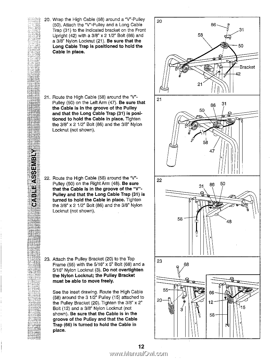
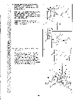
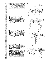
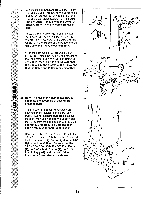
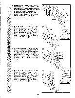
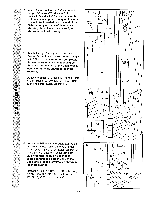
20. Wrap the High Cable (58) around a "V"-Pulley 20 (50). Attach the "V"-Pulley and a Long Cable Trap (31) to the indicated bracket on the Front Upright (42) with a 3/8" x 2 1/2" Bolt (86) and a 3/8" Nylon Locknut (21). Be sure that the Long Cable Trap is positioned to hold the Cable in place. 21. Route the High Cable (58) around the "V"Pulley (50) on the Left Arm (47). Be sure that 21 the Cable is in the groove of the Pulley and that the Long Cable Trap (31) is posi- tioned to hold the Cable in place. Tighten the 3/8" x 2 1/2" Bolt (86) and the 3/8" Nylon Locknut (not shown). 86 , 31 58 , 50 , 21 III Bracket 42 86 31 50 elA 58 47 ill 22. Route the High Cable (58) around the "V"Pulley (50) on the Right Arm (48). Be sure 22 that the Cable is in the groove of the "V"- Pulley and that the Long Cable Trap (31) is turned to hold the Cable in place. Tighten the 3/8" x 2 1/2" Bolt (86) and the 3/8" Nylon Locknut (not shown). 31 86 50 58 • 48 \\ 23. Attach the Pulley Bracket (20) to the Top Frame (55) with the 5/16" x 5" Bolt (68) and a 23 08 5/16" Nylon Locknut (3). Do not overtighten the Nylon Locknut; the Pulley Bracket \\/ must be able to move freely. See the inset drawing. Route the High Cable 55 66 (58) around the 3 1/2" Pulley (15) attached to the Pulley Bracket (20). Tighten the 3/8" x 2" 20 . ' 12 Bolt (12) and a 3/8" Nylon Locknut (not 3 \\\ 15 shown). Be sure that the Cable is in the 58 groove of the Pulley and that the Cable Trap (66) is turned to hold the Cable in . place. 12
-
 1
1 -
2
-
3
-
4
-
5
-
6
-
 7
7 -
 8
8 -
 9
9 -
 10
10 -
 11
11 -
 12
12 -
 13
13 -
 14
14 -
 15
15 -
 16
16 -
 17
17 -
18
-
19
-
20
-
21
-
22
-
23
-
24
-
25
-
26
-
27
-
28
 |
 |