Weider Pro 9645 English Manual - Page 8
Locate, parts, labeled, ASSEMBLY., tighten, Nylon, Locknut., Press, pivot, freely., tight, Plastic,
 |
View all Weider Pro 9645 manuals
Add to My Manuals
Save this manual to your list of manuals |
Page 8 highlights
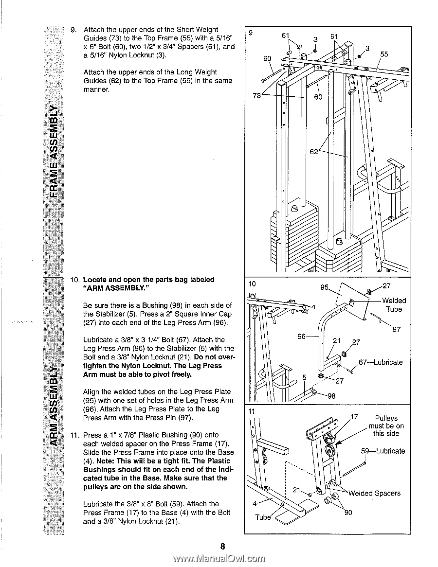
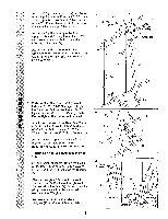
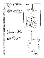
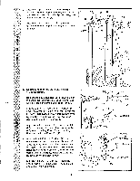
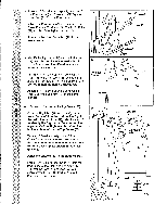
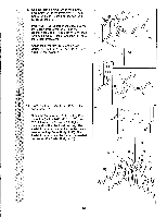
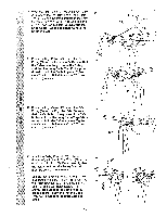
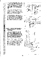
Attach the upper ends of the Short Weight Guides (73) to the Top Frame (55) with a 5/16" x 6" Bolt (60), two 1/2" x 3/4" Spacers (61), and a 5/16" Nylon Locknut (3). Attach the upper ends of the Long Weight Guides (62) to the Top Frame (55) in the same manner. 9 61 3 61 60 1O. VtimPAp' r- 13 • 3 e/ 55 73 AIIIll O 60 a 0 I 0 62 a 4 kt a 8 10. Locate and open the parts bag labeled "ARM ASSEMBLY." 10 Be sure there is a Bushing (98) in each side of the Stabilizer (5). Press a 2" Square Inner Cap (27) into each end of the Leg Press Arm (96). Lubricate a 3/8" x 3 1/4" Bolt (67). Attach the Leg Press Arm (96) to the Stabilizer (5) with the Bolt and a 3/8" Nylon Locknut (21). Do not overtighten the Nylon Locknut. The Leg Press Arm must be able to pivot freely. Align the welded tubes on the Leg Press Plate (95) with one set of holes in the Leg Press Arm (96). Attach the Leg Press Plate to the Leg 11 Press Arm with the Press Pin (97). 11. Press a 1" x 7/8" Plastic Bushing (90) onto each welded spacer on the Press Frame (17). Slide the Press Frame into place onto the Base (4). Note: This will be a tight fit. The Plastic Bushings should fit on each end of the indicated tube in the Base. Make sure that the pulleys are on the side shown. Lubricate the 3/8" x 8" Bolt (59). Attach the Press Frame (17) to the Base (4) with the Bolt and a 3/8" Nylon Locknut (21). 4 Tube 8 95 96 21 27 27 Welded Tube 97 67-Lubricate 5 27 98 0 0 0 0 17 Pulleys must be on this side 59-Lubricate 21 Welded Spacers 90
-
 1
1 -
2
-
 3
3 -
 4
4 -
 5
5 -
 6
6 -
 7
7 -
 8
8 -
 9
9 -
 10
10 -
 11
11 -
 12
12 -
 13
13 -
14
-
15
-
16
-
17
-
18
-
19
-
20
-
21
-
22
-
23
-
24
-
25
-
26
-
27
-
28
 |
 |