Yamaha RX-V373BL User Manual - Page 15
Connecting speakers, 1-channel system
 |
View all Yamaha RX-V373BL manuals
Add to My Manuals
Save this manual to your list of manuals |
Page 15 highlights
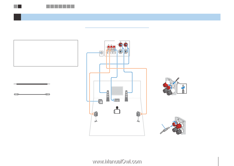
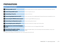
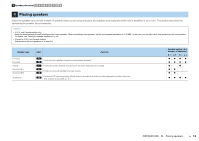
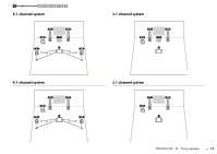
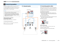
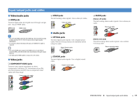
1 2 Speaker connections 3 4 5 6 7 8 9 2 Connecting speakers Connect the speakers placed in your room to the unit. The following diagrams provide connections for a 5.1-channel system as an example. For other systems, connect speakers while referring to the connection diagram for the 5.1-channel system. Caution • Remove the unit's power cable from an AC wall outlet and turn off the subwoofer before connecting the speakers. • Ensure that the core wires of the speaker cable do not touch one another or come into contact with the unit's metal parts. Doing so may damage the unit or the speakers. If the speaker cables short circuit, "Check SP Wires" will appear on the front display when the unit is turned on. Cables required for connection (commercially available) Speaker cables (x the number of speakers) + + - - Audio pin cable (x1: for connecting a subwoofer) 5.1-channel system The unit (rear) SPEAKERS SURROUND CENTER FRONT SUBWOOFER 1 2 9 3 4 5 ■ Connecting speaker cables Speaker cables have two wires. One is for connecting the negative (-) terminal of the unit and the speaker, and the other is for the positive (+) terminal. If the wires are colored to prevent confusion, connect the black wire to the negative and the other wire to the positive terminal. (Connecting front speakers) a Remove approximately 10 mm (3/8") of insulation from the ends of the speaker cable and twist the bare wires of the cable firmly together. b Loosen the speaker terminal. c Insert the bare wires of the cable into the gap on the side (upper right or bottom left) of the terminal. d Tighten the terminal. + (red) c b FRONT - (black) da Using a banana plug (U.S.A., Canada, Australia and General models only) a Tighten the speaker terminal. b Insert a banana plug into the end of the terminal. a Banana plug FRONT b PREPARATIONS ➤ Connecting speakers En 15
-
 1
1 -
2
-
3
-
4
-
5
-
6
-
7
-
8
-
9
-
 10
10 -
 11
11 -
 12
12 -
 13
13 -
 14
14 -
 15
15 -
 16
16 -
 17
17 -
 18
18 -
 19
19 -
 20
20 -
21
-
22
-
23
-
24
-
25
-
26
-
27
-
28
-
29
-
30
-
31
-
32
-
33
-
34
-
35
-
36
-
37
-
38
-
39
-
40
-
41
-
42
-
43
-
44
-
45
-
46
-
47
-
48
-
49
-
50
-
51
-
52
-
53
-
54
-
55
-
56
-
57
-
58
-
59
-
60
-
61
-
62
-
63
-
64
-
65
-
66
-
67
-
68
-
69
-
70
-
71
-
72
-
73
-
74
-
75
-
76
-
77
-
78
-
79
-
80
-
81
-
82
-
83
 |
 |