Yamaha RX-V373BL User Manual - Page 9
Rear panel, AV OUT jacks - model
 |
View all Yamaha RX-V373BL manuals
Add to My Manuals
Save this manual to your list of manuals |
Page 9 highlights
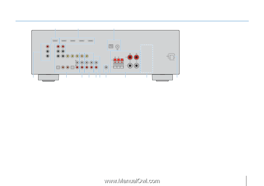
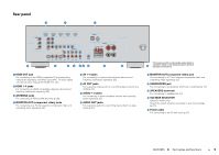
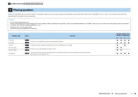
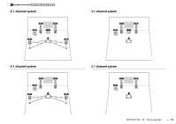
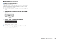
Rear panel 1 2 3 COMPONENT VIDEO PR ARC HDMI OUT PR (BD/DVD) HDMI 1 HDMI 2 PB PB Y MONITOR OUT Y COMPONENT VIDEO VIDEO HDMI 3 HDMI 4 MONITOR OUT ANTENNA AM FM SPEAKERS SURROUND CENTER FRONT 4 OPTICAL AV 1 COAXIAL AV 2 COAXIAL (CD) AV 3 OPTICAL ( TV ) AV 4 AV 5 AV OUT AUDIO 1 AUDIO 2 AUDIO OUT SUBWOOFER 5 6 7 89 0 A B 1 HDMI OUT jack For connecting to an HDMI-compatible TV and outputting video/audio signals (p.18). When using ARC, TV audio signal can also be input through the HDMI OUT jack. 2 HDMI 1-4 jacks For connecting to HDMI-compatible playback devices and inputting video/audio signals (p.23). 3 ANTENNA jacks For connecting to FM and AM antennas (p.26). 4 MONITOR OUT (component video) jacks For connecting to a TV that supports component video and outputting video signals (p.22). 5 AV 1-5 jacks For connecting to video/audio playback devices and inputting video/audio signals (p.23). 6 AV OUT jacks For outputting video/audio to a recording device (such as a VCR) (p.27). 7 AUDIO 1-2 jacks For connecting to audio playback devices and inputting audio signals (p.25). 8 AUDIO OUT jacks For outputting audio to a recording device (such as tape deck) (p.27). * The area around the video/audio output jacks is C marked in white on the actual product to prevent improper connections. 9 MONITOR OUT (composite video) jack For connecting to a TV that supports composite video and outputting video signals (p.22). 0 SUBWOOFER jack For connecting to a subwoofer (with built-in amplifier) (p.15). A SPEAKERS terminals For connecting to speakers (p.15). B VOLTAGE SELECTOR (General model only) Selects the switch position according to your local voltage (p.27). C Power cable For connecting to an AC wall outlet (p.27). FEATURES ➤ Part names and functions En 9
-
 1
1 -
2
-
3
-
 4
4 -
 5
5 -
 6
6 -
 7
7 -
 8
8 -
 9
9 -
 10
10 -
 11
11 -
 12
12 -
 13
13 -
 14
14 -
15
-
16
-
17
-
18
-
19
-
20
-
21
-
22
-
23
-
24
-
25
-
26
-
27
-
28
-
29
-
30
-
31
-
32
-
33
-
34
-
35
-
36
-
37
-
38
-
39
-
40
-
41
-
42
-
43
-
44
-
45
-
46
-
47
-
48
-
49
-
50
-
51
-
52
-
53
-
54
-
55
-
56
-
57
-
58
-
59
-
60
-
61
-
62
-
63
-
64
-
65
-
66
-
67
-
68
-
69
-
70
-
71
-
72
-
73
-
74
-
75
-
76
-
77
-
78
-
79
-
80
-
81
-
82
-
83
 |
 |