Zenith XBV613 Service Manual - Page 18
Servo Circuit
 |
UPC - 719192169715
View all Zenith XBV613 manuals
Add to My Manuals
Save this manual to your list of manuals |
Page 18 highlights
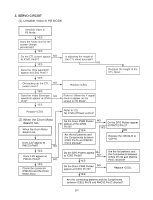
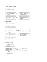
3. SERVO CIRCUIT (1) Unstable Video in PB MODE Unstable Video in PB Mode. YES Does the Noise level of the screen change periodically? YES Do the CTL pulses appear NO at IC501 Pin97? YES Does the CFG waveform appear at IC501 Pin87? YES On tracking do the CTL NO pulses move? YES Does the Video Envelope NO waveform appear at IC501 Pin9? YES Replace IC501. (2) When the Drum Motor (2) doesn't run. When the Drum Motor doesn't run, Does 12V appear at PMC01 Pin8? NO YES Does 2.8V appear at PMC01 Pin12? NO YES Check the connector (PMC01) and the Drum Motor Ass'y. Is adjusting the height of the CTL Head accurate? NO Readjust the height of the CTL Head. Replace IC501. Refer to "When the Y signal doesn't appear on the screen in PB Mode". Refer to "(2) No 12VA of Power section" Do the Drum PWM Pulses appear at the IC501 Pin76? YES Are the foil patterns and the Components between IC501 Pin76 and PMC01 Pin12 shorted? NO YES Do the DFG Pulses appear at PMC01 Pin11? NO Replace the DRUM-M or CAP-M. Do the DFG Pulses appear at IC501 Pin90? NO YES Do the Drum PWM Pulses NO appear at IC501 Pin76? Are the foil patterns and the Components between IC501 Pin 90 and PMC01 Pin11 shorted? Replace IC501. YES Are the connecting patterns and the Components between IC501 Pin76 and PMC01 Pin12 shorted? 3-7
-
 1
1 -
2
-
3
-
4
-
5
-
6
-
7
-
8
-
9
-
10
-
11
-
12
-
 13
13 -
 14
14 -
 15
15 -
 16
16 -
 17
17 -
 18
18 -
 19
19 -
 20
20 -
 21
21 -
 22
22 -
 23
23 -
24
-
25
-
26
-
27
-
28
-
29
-
30
-
31
-
32
-
33
-
34
-
35
-
36
-
37
-
38
-
39
-
40
-
41
-
42
-
43
-
44
-
45
-
46
-
47
-
48
-
49
-
50
-
51
-
52
-
53
-
54
-
55
-
56
-
57
-
58
-
59
-
60
-
61
-
62
-
63
-
64
-
65
-
66
-
67
-
68
-
69
-
70
-
71
-
72
-
73
-
74
-
75
-
76
-
77
-
78
-
79
-
80
-
81
-
82
-
83
-
84
-
85
-
86
-
87
-
88
-
89
-
90
-
91
-
92
-
93
-
94
-
95
-
96
-
97
-
98
-
99
-
100
-
101
-
102
-
103
-
104
-
105
-
106
-
107
-
108
-
109
-
110
-
111
-
112
-
113
-
114
-
115
-
116
-
117
-
118
-
119
-
120
-
121
-
122
-
123
-
124
-
125
-
126
-
127
-
128
 |
 |