Zenith XBV613 Service Manual - Page 88
Deck Mechanism Disassembly
 |
UPC - 719192169715
View all Zenith XBV613 manuals
Add to My Manuals
Save this manual to your list of manuals |
Page 88 highlights
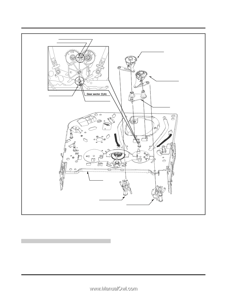
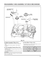
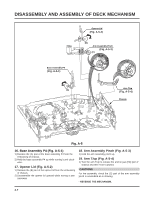
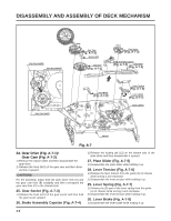
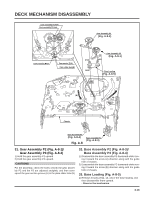
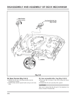
DECK MECHANISM DISASSEMBLY Gear assembly P2 Hole Gear assembly P3 Hole Gear Assembly P3 (Fig. A-8-2) Lever Tension Boss Plate slider Hole(B) (H12) (H13) Gear Assembly P2 (Fig. A-8-1) (H14) Base Loading (Fig. A-8-5) (B) (A) Chassis Base Assembly P3 (Fig. A-8-4) Fig. A-8 Base Assembly P2 (Fig. A-8-3) 31. Gear Assembly P2 (Fig. A-8-1)/ Gear Assembly P3 (Fig. A-8-2) 1) Hold the gear assembly P2 upward. 2) Hold the gear assembly P3 upward. CAUTIONS For the assembly, check the holes of both the gear assembly P2 and the P3 are adjusted straightly, and then correspond the gear section groove (A) to the plate slider hole (B). 32. Base Assembly P2 (Fig. A-8-3)/ Base Assembly P3 (Fig. A-8-4) 1) Disassemble the base assembly P2 downward while moving it toward the arrow (A) direction along with the guide hole of chassis. 2) Disassemble the base assembly P2 downward while moving it toward the arrow (B) direction along with the guide hole of chassis. 33. Base Loading (Fig. A-8-5) 1) Release 3 hooks (H12, 13, 14) of the base loading, and then disassemble them upward. - Reverse the mechanism. 4-10
-
 1
1 -
2
-
3
-
4
-
5
-
6
-
7
-
8
-
9
-
10
-
11
-
12
-
13
-
14
-
15
-
16
-
17
-
18
-
19
-
20
-
21
-
22
-
23
-
24
-
25
-
26
-
27
-
28
-
29
-
30
-
31
-
32
-
33
-
34
-
35
-
36
-
37
-
38
-
39
-
40
-
41
-
42
-
43
-
44
-
45
-
46
-
47
-
48
-
49
-
50
-
51
-
52
-
53
-
54
-
55
-
56
-
57
-
58
-
59
-
60
-
61
-
62
-
63
-
64
-
65
-
66
-
67
-
68
-
69
-
70
-
71
-
72
-
73
-
74
-
75
-
76
-
77
-
78
-
79
-
80
-
81
-
82
-
 83
83 -
 84
84 -
 85
85 -
 86
86 -
 87
87 -
 88
88 -
 89
89 -
 90
90 -
 91
91 -
 92
92 -
 93
93 -
94
-
95
-
96
-
97
-
98
-
99
-
100
-
101
-
102
-
103
-
104
-
105
-
106
-
107
-
108
-
109
-
110
-
111
-
112
-
113
-
114
-
115
-
116
-
117
-
118
-
119
-
120
-
121
-
122
-
123
-
124
-
125
-
126
-
127
-
128
 |
 |