Zenith XBV613 Service Manual - Page 95
X-distance Adjustment
 |
UPC - 719192169715
View all Zenith XBV613 manuals
Add to My Manuals
Save this manual to your list of manuals |
Page 95 highlights
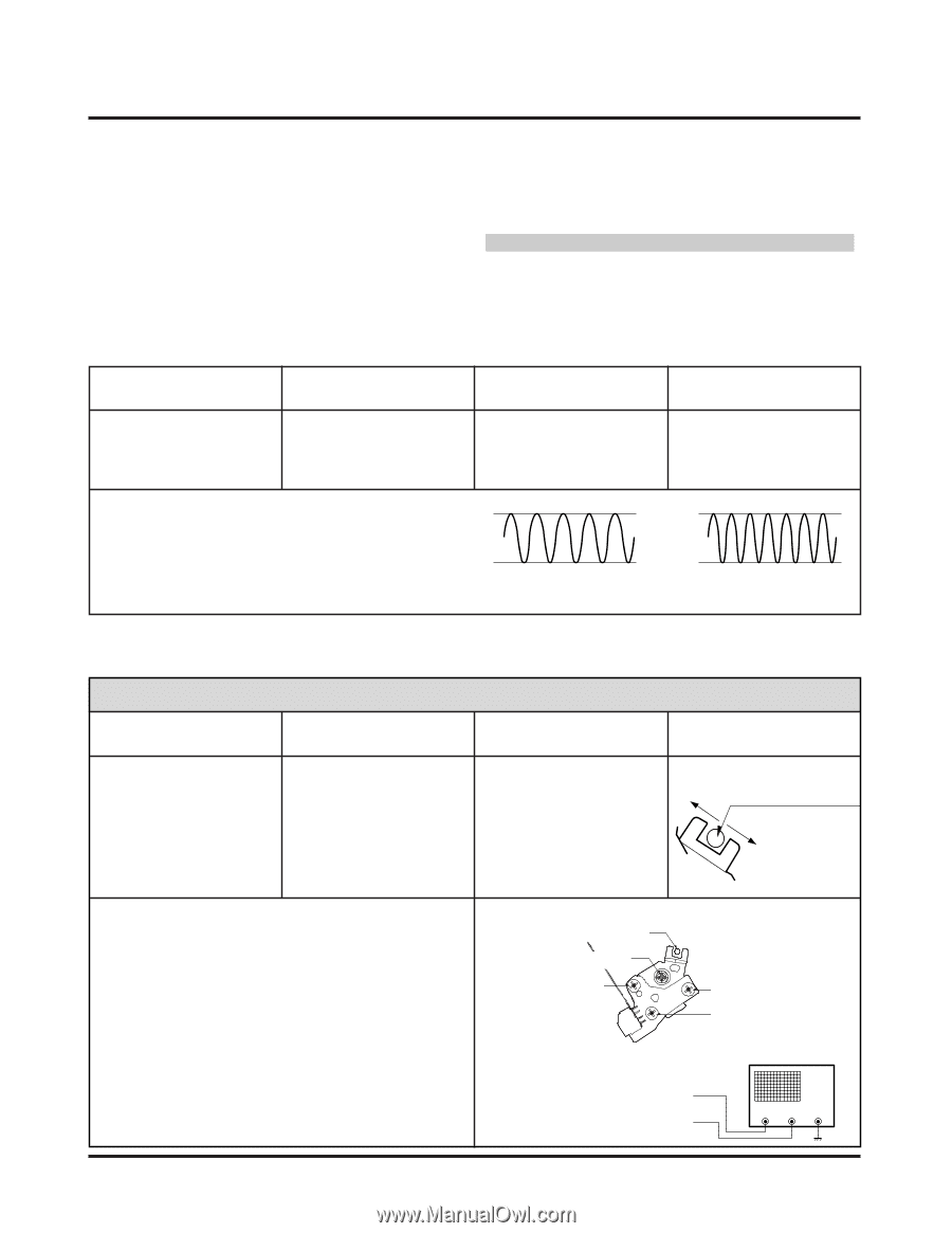
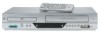
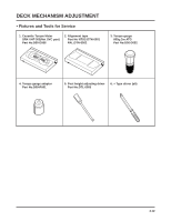
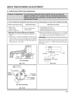
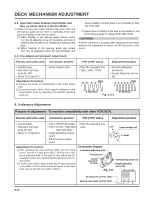
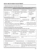
DECK MECHANISM ADJUSTMENT 5-2. Tape Path Check between Pinch Roller and Take up Guide (Check in the Rev Mode) 1) Check the tape pass status between the pinch roller and the take-up guide.(Check there is crumpling of the tape pass and folding of the take-up guide.) 1) (1) When holding of the take-up guide bottom occurs Turn the tilt adjusting screw (C) clockwise and travel it stably to ensure there is no crumbling or folding of the tape. 1) (2) When holding of the take-up guide top occurs Turn the tilt adjusting screw (C) anti-clockwise and travel it stably to ensure there is no crumbling or folding of the tape. 1) 2) Check there is folding of the tape at the bottom or top of the take-up guide in cutting-off the REV mode CAUTIONS If the RF waveform is changed after adjusting the A/C head, perform fine adjustment to ensure the RF waveform is flattened. 5-3. Fine Adjustment (Azimuth Adjustment) Fixtures and tools used Connection position VCR (VCP) status Adjustment position • Oscilloscope • Standard test tape (only for SP) • Driver (+) Type Ø 4 • Audio Output Jack Adjustment Procedure 1) Connect the probe of Oscilloscope to the audio output jack. 2) Ensure that Audio 1KHz, 7KHz output is flattened at the maximization point by adjusting the Azimuth adjusting screw (A). • Play the standard test • Tape, 1KHz, 7KHz. 1KHz • Azimuth Adjusting Screw (A) • Height Adjusting Screw (B) 7KHz A: Maximum Fig. C-5-4 B: Minimum 6. X-distance Adjustment Purpose of adjustment : To maintain compatibility with other VCR (VCP). Fixtures and tools used Connection position VCR (VCP) status Adjustment position • Oscilloscope • Standard test tape (only for SP) • Driver (+) Type Ø 4 • CH-1: PB RF Envelope • Play the standard test • CH-2: NTSC ; SW 30Hz tape. Left PAL:SW 25Hz • Head switching output point • RF Envelope output point Grove of Base A/C Right Adjustment Procedure 1) After releasing the auto tracking, lightly turn the fixing screw. Turn the (+) type driver (Ø 3 ~ Ø 4) on the X-distance adjusting hole to the right or left. Adjust the RF envelope level to the maximum point and then fix the fixing screws. 2) For the 31mm head, adjust it with the SP tape recorded in the width of 31mm since the head travels on the tape track only for SP with the width of 58mm. Connection Diagram X-distance Adjusting Hole Fixing Screw Azimuth Adjustment Screw(A) Fig. C-6 Tilt Adjusting Screw (C) Height Adjusting Screw (B) OSCILLOSCOPE RF ENVELOPE OUTPUT POINT HEAD RF SWITCHING OUTPUT POINT CH-1 CH-2 4-17
-
 1
1 -
2
-
3
-
4
-
5
-
6
-
7
-
8
-
9
-
10
-
11
-
12
-
13
-
14
-
15
-
16
-
17
-
18
-
19
-
20
-
21
-
22
-
23
-
24
-
25
-
26
-
27
-
28
-
29
-
30
-
31
-
32
-
33
-
34
-
35
-
36
-
37
-
38
-
39
-
40
-
41
-
42
-
43
-
44
-
45
-
46
-
47
-
48
-
49
-
50
-
51
-
52
-
53
-
54
-
55
-
56
-
57
-
58
-
59
-
60
-
61
-
62
-
63
-
64
-
65
-
66
-
67
-
68
-
69
-
70
-
71
-
72
-
73
-
74
-
75
-
76
-
77
-
78
-
79
-
80
-
81
-
82
-
83
-
84
-
85
-
86
-
87
-
88
-
89
-
 90
90 -
 91
91 -
 92
92 -
 93
93 -
 94
94 -
 95
95 -
 96
96 -
 97
97 -
 98
98 -
 99
99 -
 100
100 -
101
-
102
-
103
-
104
-
105
-
106
-
107
-
108
-
109
-
110
-
111
-
112
-
113
-
114
-
115
-
116
-
117
-
118
-
119
-
120
-
121
-
122
-
123
-
124
-
125
-
126
-
127
-
128
 |
 |