Zenith XBV613 Service Manual - Page 96
Adjustment after Drum Assembly Video Heads, Check of Traveling Device after Deck Assembly
 |
UPC - 719192169715
View all Zenith XBV613 manuals
Add to My Manuals
Save this manual to your list of manuals |
Page 96 highlights
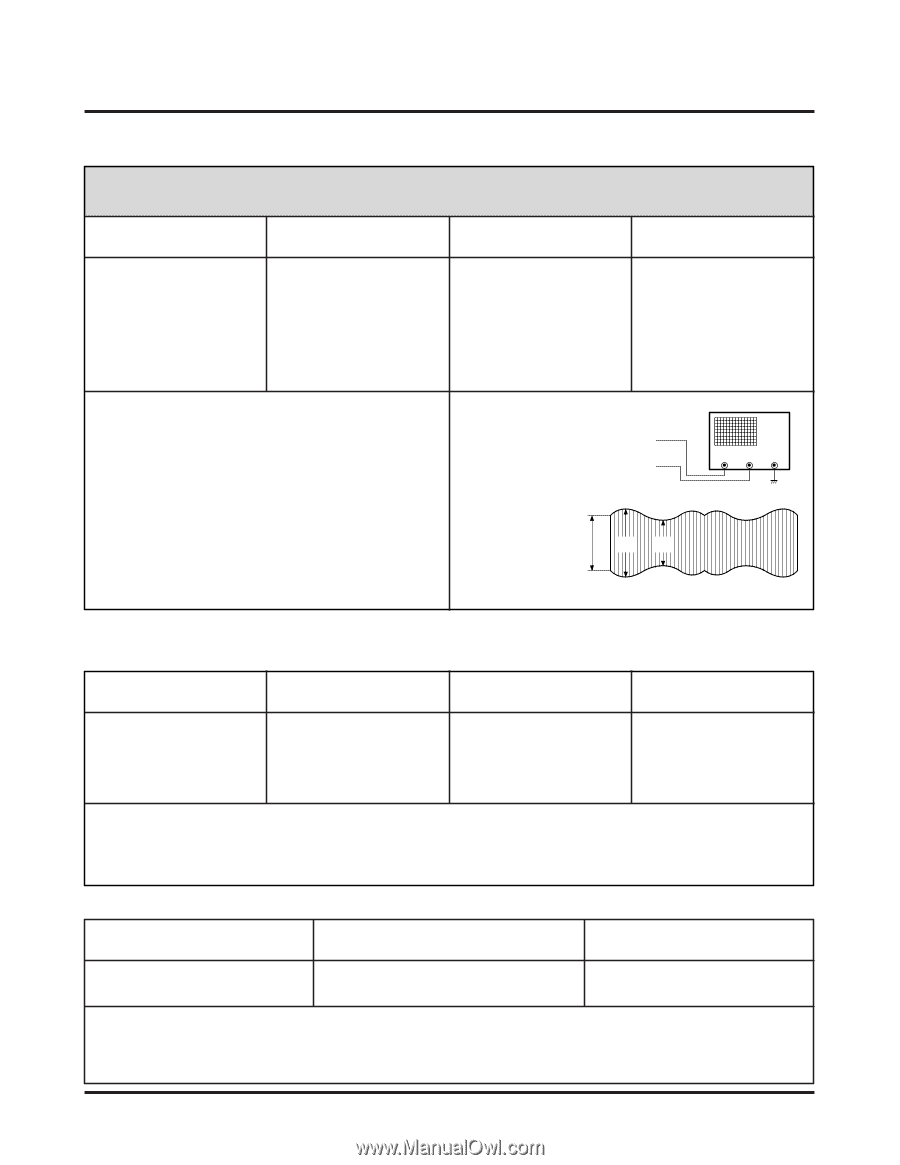
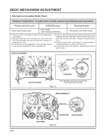
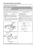
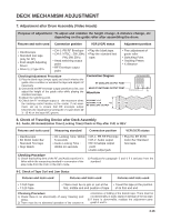
DECK MECHANISM ADJUSTMENT 7. Adjustment after Drum Assembly (Video Heads) Purpose of adjustment : To adjust and stabilize the height change, X-distance change, etc depending on the guide roller after assembling the drum. Fixtures and tools used Connection position VCR (VCP) status Adjustment position • Oscilloscope • Standard test tape (only for SP) • Post Height Adjusting Driver • Driver (+) Type Ø 5 • CH-1: PB RF Envelope • CH-2: NTSC : SW 30Hz PAL:SW 25Hz • Head switching output point • RF Envelope output point • Play the blank tape. • Play the standard test tape. • Fine adjustment of guide roller • Switching Point • Tracking Preset • X-distance Checking/Adjustment Procedure 1) Play the blank tape (empty tape) and check whether the guide roller crumbles or wrinkles the tape and adjust it if necessary. 2) Check that the RF envelope output waveform is flat, and adjust the height of the guide roller while playing the standard test tape. 3) Adjust the switching point. 4) Check the RF envelope output is the maximum when the tracking control locates at the center. If not maximum, set up to ensure that RF envelope output becomes the maximum by turning the (+) type driver (Ø 3 ~ Ø 4) on the base A/C groove. Connection Diagram RF ENVELOPE OUTPUT POINT HEAD RF SWITCHING OUTPUT POINT Waveform V1/V MAX = 0.7 V1/V MAX = 0.8 V1 RF ENVELOPE OUTPUT V1 V2 OSCILLOSCOPE CH-1 CH-2 8. Check of Traveling Device after Deck Assembly 8-1. Audio, RF Normalization Time (Locking Time) Check in Play after CUE or REV Fixtures and tools used Measuring standard Connection position VCR (VCP) status • Oscilloscope • 6H 3KHz Color Bar Standard Test tape • Stop Watch • RF Locking Time: Within • CH-1: PB RF Envelope 5 seconds • CH-2: Audio output • Audio Locking Time : • RF Envelope output Within 10 seconds point • Audio output jack • Play the 6H 3KHz Color Bar Standard Test tape. Checking Procedure 1) Check that locking time of the RF and Audio waveform is fallen within the measuring standard in conversion of the play mode from the CUE or the REV mode. 2) Readjust the paragraph 5 and 6 if it deviates from the standard. 8-2. Check of Tape Curl and Jam Status Fixtures and tools used Fixtures and tools used Fixtures and tools used • T-160 Tape • T-120 Tape • There must be no jam or curl at the • Travel the tape at the position first, middle and end position of tape. of its first and end. Checking Procedure 1) Check there is no abnormality of every traveling post status. 2) There must be no abnormal operation of the counter in occurrence of folding of the bottom tape. There must be not abnormality of audio signal in damage of the top tape. 3) If there is abnormality, readjust the adjustment paragraph 4 and 5. 4-18
-
 1
1 -
2
-
3
-
4
-
5
-
6
-
7
-
8
-
9
-
10
-
11
-
12
-
13
-
14
-
15
-
16
-
17
-
18
-
19
-
20
-
21
-
22
-
23
-
24
-
25
-
26
-
27
-
28
-
29
-
30
-
31
-
32
-
33
-
34
-
35
-
36
-
37
-
38
-
39
-
40
-
41
-
42
-
43
-
44
-
45
-
46
-
47
-
48
-
49
-
50
-
51
-
52
-
53
-
54
-
55
-
56
-
57
-
58
-
59
-
60
-
61
-
62
-
63
-
64
-
65
-
66
-
67
-
68
-
69
-
70
-
71
-
72
-
73
-
74
-
75
-
76
-
77
-
78
-
79
-
80
-
81
-
82
-
83
-
84
-
85
-
86
-
87
-
88
-
89
-
90
-
 91
91 -
 92
92 -
 93
93 -
 94
94 -
 95
95 -
 96
96 -
 97
97 -
 98
98 -
 99
99 -
 100
100 -
 101
101 -
102
-
103
-
104
-
105
-
106
-
107
-
108
-
109
-
110
-
111
-
112
-
113
-
114
-
115
-
116
-
117
-
118
-
119
-
120
-
121
-
122
-
123
-
124
-
125
-
126
-
127
-
128
 |
 |