Zenith XBV613 Service Manual - Page 94
Audio/Control A/C Head Adjustment - specs
 |
UPC - 719192169715
View all Zenith XBV613 manuals
Add to My Manuals
Save this manual to your list of manuals |
Page 94 highlights
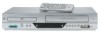
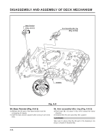
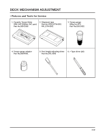
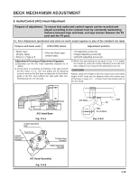
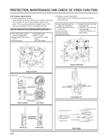
DECK MECHANISM ADJUSTMENT 5. Audio/Control (A/C) Head Adjustment Purpose of adjustment : To ensure that audio and control signals can be recorded and played according to the contract tract by constantly maintaining distance between tape and head, and tape tension between the P3 post and the P4 post. 5-1. Prior Adjustment (performed only when no audio output appears in play of the standard test tape) Fixtures and tools used VCR (VCP) status Adjustment position • Blank Tape (Empty Tape) • Driver (+) Type ø 5 • Play the blank tape (empty tape). Adjustment Procedure/Adjustment Diagrams 1) Basically use the A/C head assembly adjusted as in SPEC. 2) Check there is crumpling and folding of the tape around the A/C head. If it is, Turn and adjust the tilt adjusting screw to ensure that the tape corresponds to the bottom guide of the P4, and recheck the tape path after proceeding play for 4-5 seconds. • Tilt adjusting screw (C) • Height adjusting screw (B) • Azimuth adjusting screw (A) 3) Where the tape bottom is not equal to Fig. C-5-3, Adjust the height by using the height adjusting screw (B) and then readjust it by using the tilt adjusting screw (C). CAUTIONS Always check the height of the A/C head since most ideal height of A/C head can be obtained when the bottom part of the tape is away 0.2 ~ 0.25mm from the bottom part of the A/C head. 8.3 A/C Head Base Fig. C-5-1 X-Value Adjustment Hole Fixed Screw Azimuth Adjustment Screw(A) Tilt Adjustment Screw(C) Height Adjustment Screw(B) A/C Head Assembly Fig. C-5-2 A/C Head P4 Tape 0.2~0.25mm Fig. C-5-3 Tape 4-16
-
 1
1 -
2
-
3
-
4
-
5
-
6
-
7
-
8
-
9
-
10
-
11
-
12
-
13
-
14
-
15
-
16
-
17
-
18
-
19
-
20
-
21
-
22
-
23
-
24
-
25
-
26
-
27
-
28
-
29
-
30
-
31
-
32
-
33
-
34
-
35
-
36
-
37
-
38
-
39
-
40
-
41
-
42
-
43
-
44
-
45
-
46
-
47
-
48
-
49
-
50
-
51
-
52
-
53
-
54
-
55
-
56
-
57
-
58
-
59
-
60
-
61
-
62
-
63
-
64
-
65
-
66
-
67
-
68
-
69
-
70
-
71
-
72
-
73
-
74
-
75
-
76
-
77
-
78
-
79
-
80
-
81
-
82
-
83
-
84
-
85
-
86
-
87
-
88
-
 89
89 -
 90
90 -
 91
91 -
 92
92 -
 93
93 -
 94
94 -
 95
95 -
 96
96 -
 97
97 -
 98
98 -
 99
99 -
100
-
101
-
102
-
103
-
104
-
105
-
106
-
107
-
108
-
109
-
110
-
111
-
112
-
113
-
114
-
115
-
116
-
117
-
118
-
119
-
120
-
121
-
122
-
123
-
124
-
125
-
126
-
127
-
128
 |
 |