Zenith XBV613 Service Manual - Page 87
Gear Sector Fig. A-7-3, Brake Assembly Capstan Fig. A-7-4, Plate Slider Fig. A-7-5, Lever Tension
 |
UPC - 719192169715
View all Zenith XBV613 manuals
Add to My Manuals
Save this manual to your list of manuals |
Page 87 highlights
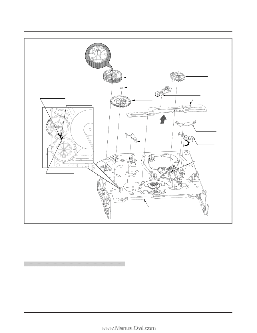
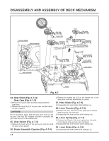
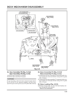
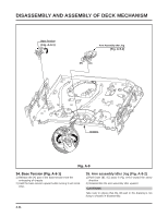
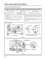
DISASSEMBLY AND ASSEMBLY OF DECK MECHANISM Gear Cam Hole(B) Gear Drive Hole(A) (H10) Gear Cam (Fig. A-7-2) (W2) Washer (W2) Gear Drive (L2) (Fig. A-7-1) (H11) Gear Sector (Fig. A-7-3) Brake Assembly Capstan (Fig. A-7-4) Plate Slider (Fig. A-7-5) Gear Cam Hole(C) Lever Brack (Fig. A-7-8) Lever Tension (Fig. A-7-6) (B) Lever spring (Fig. A-7-7) Base Loading (A) Chassis Fig. A-7 24. Gear Drive (Fig. A-7-1)/ Gear Cam (Fig. A-7-2) 1) Remove the washer (W2) and then disassemble the gear drive. 2) Release the hook (H10) of the gear cam and then disassemble it upward. CAUTIONS For the assembly, adjust both the gear driver hole (A) and the gear cam hole (B) straightly and then correspond the gear cam hole (C) to the chassis hole. 25. Gear Sector (Fig. A-7-3) 1) Release the hook (H11) of the gear sector and then hold the gear sector upward. 26. Brake Assembly Capstan (Fig. A-7-4) 1) Release the locking tab (L2) on the bottom side of the plate slider and then disassemble it upward. 27. Plate Slider (Fig. A-7-5) 1) Disassemble the plate slider while holding it up. 28. Lever Tension (Fig. A-7-6) 1) Release the lever tension from the guide (A) of chassis while turning it anti-clockwise. 2) Disassemble the lever tension while holding it up. 29. Lever Spring (Fig. A-7-7) 1) Release the (B) part of the lever spring from the guide (A) of chassis while turning it anti-clockwise. 2) Disassemble the lever tension while holding it up. 30. Lever Brake (Fig. A-7-8) 1) Disassemble the lever brake while holding it up. 4-9
-
 1
1 -
2
-
3
-
4
-
5
-
6
-
7
-
8
-
9
-
10
-
11
-
12
-
13
-
14
-
15
-
16
-
17
-
18
-
19
-
20
-
21
-
22
-
23
-
24
-
25
-
26
-
27
-
28
-
29
-
30
-
31
-
32
-
33
-
34
-
35
-
36
-
37
-
38
-
39
-
40
-
41
-
42
-
43
-
44
-
45
-
46
-
47
-
48
-
49
-
50
-
51
-
52
-
53
-
54
-
55
-
56
-
57
-
58
-
59
-
60
-
61
-
62
-
63
-
64
-
65
-
66
-
67
-
68
-
69
-
70
-
71
-
72
-
73
-
74
-
75
-
76
-
77
-
78
-
79
-
80
-
81
-
 82
82 -
 83
83 -
 84
84 -
 85
85 -
 86
86 -
 87
87 -
 88
88 -
 89
89 -
 90
90 -
 91
91 -
 92
92 -
93
-
94
-
95
-
96
-
97
-
98
-
99
-
100
-
101
-
102
-
103
-
104
-
105
-
106
-
107
-
108
-
109
-
110
-
111
-
112
-
113
-
114
-
115
-
116
-
117
-
118
-
119
-
120
-
121
-
122
-
123
-
124
-
125
-
126
-
127
-
128
 |
 |