Zenith XBV613 Service Manual - Page 82
Lever Assembly S/W Fig. A-2-6
 |
UPC - 719192169715
View all Zenith XBV613 manuals
Add to My Manuals
Save this manual to your list of manuals |
Page 82 highlights
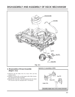
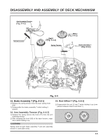
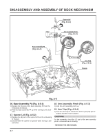
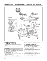
DISASSEMBLY AND ASSEMBLY OF DECK MECHANISM 2. Disassembly of Plate Top (Fig. A-2-1) 1) Separate the right part while leaning back the (B) part of the plate top toward the arrow direction. 2) Separate the left part while leaning back the (B') part of the plate top toward the arrow direction. (Tool used: Tool such as (-) driver, auger, etc with pointed or flat end) CAUTIONS Assemble while pressing the (C), (C') part after corresponding them as in drawing. 4. Disassembly of Gear Assembly Rack F/L (Fig. A-2-3) 1) Separate the hook (H3) while leaning ahead the hook (3) after moving the gear assembly rack F/L toward the arrow (A) direction. 2) Separate the gear assembly rack F/L toward the arrow (B) direction. CAUTIONS For the assembly, correspond the gear part of gear assembly rack F/L to the gear drive. Gear Rack F/L (C') (C) (B') (B) Gear Drive 3. Holder Assembly CST (Fig. A-2-2) 1) Firstly separate the left part from the groove on the (D) part of chassis while moving the holder assembly CST toward the arrow direction. Holder Assembly CST (D) Chassis 5. Opener Door (Fig. A-2-4) 1) Separate the opener door ahead from the guide hole of chassis while turning it clockwise. 6. Arm Assembly F/L (Fig. A-2-5) 1) Firstly separate the left part of the arm assembly F/L from the groove of chassis while pushing the arm assembly F/L toward the arrow direction. 2) Separate the right part from the groove of chassis.). 7. Lever Assembly S/W (Fig. A-2-6) 1) Separate the lever assembly S/W while pushing it toward the arrow direction after removing the hook (4) on the left side of chassis. Chassis 2) Separate the right part from each groove of chassis CAUTIONS (H4) Assemble by inserting the left part after firstly inserting the (E) part of the holder assembly CST into the groove on the (E') part of chassis. 4-4
-
 1
1 -
2
-
3
-
4
-
5
-
6
-
7
-
8
-
9
-
10
-
11
-
12
-
13
-
14
-
15
-
16
-
17
-
18
-
19
-
20
-
21
-
22
-
23
-
24
-
25
-
26
-
27
-
28
-
29
-
30
-
31
-
32
-
33
-
34
-
35
-
36
-
37
-
38
-
39
-
40
-
41
-
42
-
43
-
44
-
45
-
46
-
47
-
48
-
49
-
50
-
51
-
52
-
53
-
54
-
55
-
56
-
57
-
58
-
59
-
60
-
61
-
62
-
63
-
64
-
65
-
66
-
67
-
68
-
69
-
70
-
71
-
72
-
73
-
74
-
75
-
76
-
 77
77 -
 78
78 -
 79
79 -
 80
80 -
 81
81 -
 82
82 -
 83
83 -
 84
84 -
 85
85 -
 86
86 -
 87
87 -
88
-
89
-
90
-
91
-
92
-
93
-
94
-
95
-
96
-
97
-
98
-
99
-
100
-
101
-
102
-
103
-
104
-
105
-
106
-
107
-
108
-
109
-
110
-
111
-
112
-
113
-
114
-
115
-
116
-
117
-
118
-
119
-
120
-
121
-
122
-
123
-
124
-
125
-
126
-
127
-
128
 |
 |
