Zenith XBV613 Service Manual - Page 85
Opener Lid Fig. A-5-2, Arm Assembly Pinch Fig. A-5-3, Arm T/up Fig. A-5-4
 |
UPC - 719192169715
View all Zenith XBV613 manuals
Add to My Manuals
Save this manual to your list of manuals |
Page 85 highlights
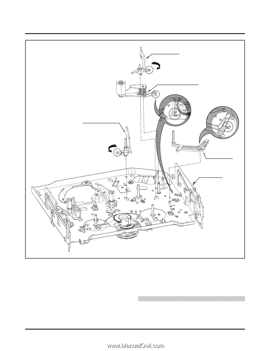
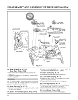
DISASSEMBLY AND ASSEMBLY OF DECK MECHANISM Opener Lid (Fig. A-5-2) (B) Arm Assembly Pinch (Fig. A-5-3) (C) Base Assembly P4 (Fig. A-5-1) (A) (C) (H9) Arm T/up (Fig. A-5-4) Chassis Fig. A-5 16. Base Assembly P4 (Fig. A-5-1) 1) Release the (A) part of the base assembly P4 from the embossing of chassis. 2) Hold the base assembly P4 up while turning it anti-clockwise. 17. Opener Lid (Fig. A-5-2) 1) Release the (B) part of the opener lid from the embossing of chassis. 2) Disassemble the opener lid upward while turning it anticlockwise. 18. Arm Assembly Pinch (Fig. A-5-3) 1) Hold the arm assembly pinch up. 19. Arm T/up (Fig. A-5-4) 1) Turn the arm T/up to release the anchor jaw (H9) part of chassis and then hold it upward. CAUTIONS For the assembly, check the (C) part of the arm assembly pinch is assembled as in drawing. - REVERSE THE MECHANISM. 4-7
-
 1
1 -
2
-
3
-
4
-
5
-
6
-
7
-
8
-
9
-
10
-
11
-
12
-
13
-
14
-
15
-
16
-
17
-
18
-
19
-
20
-
21
-
22
-
23
-
24
-
25
-
26
-
27
-
28
-
29
-
30
-
31
-
32
-
33
-
34
-
35
-
36
-
37
-
38
-
39
-
40
-
41
-
42
-
43
-
44
-
45
-
46
-
47
-
48
-
49
-
50
-
51
-
52
-
53
-
54
-
55
-
56
-
57
-
58
-
59
-
60
-
61
-
62
-
63
-
64
-
65
-
66
-
67
-
68
-
69
-
70
-
71
-
72
-
73
-
74
-
75
-
76
-
77
-
78
-
79
-
 80
80 -
 81
81 -
 82
82 -
 83
83 -
 84
84 -
 85
85 -
 86
86 -
 87
87 -
 88
88 -
 89
89 -
 90
90 -
91
-
92
-
93
-
94
-
95
-
96
-
97
-
98
-
99
-
100
-
101
-
102
-
103
-
104
-
105
-
106
-
107
-
108
-
109
-
110
-
111
-
112
-
113
-
114
-
115
-
116
-
117
-
118
-
119
-
120
-
121
-
122
-
123
-
124
-
125
-
126
-
127
-
128
 |
 |