Zenith XBV613 Service Manual - Page 83
Motor Assembly L/D Fig. A-3-1, Gear Wheel Fig. A-3-2, Arm Assembly Cleaner Fig. A-3-3, Head F/E Fig
 |
UPC - 719192169715
View all Zenith XBV613 manuals
Add to My Manuals
Save this manual to your list of manuals |
Page 83 highlights
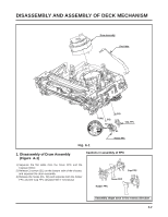
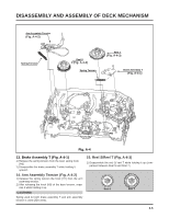
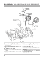
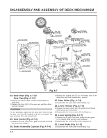
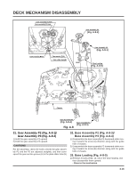
DISASSEMBLY AND ASSEMBLY OF DECK MECHANISM Head F/E (Fig. A-3-4) Arm Assembly Cleaner (Fig. A-3-3) (A) (H5) Base Assembly A/C Head (Fig. A-3-5) (S5) (A) Gear Wheel (Fig. A-3-2) Motor Assembly L/D (Fig. A-3-1) (C1) (S4) Fig. A-3 8. Motor Assembly L/D (Fig. A-3-1) 1) Take the connector (C1) connected to the Capstan motor PCB out. 2) Remove a screw (S4) of the chassis (S4) and step backward, and disassemble it while holding it up. 9. Gear Wheel (Fig. A-3-2) 1) Release the hook (H5) of the gear wheel and disassemble it upward. 10. Arm Assembly Cleaner (Fig. A-3-3) 1) Separate the (A) part of Fig. A-3-1 from the embossing of chassis, and hold it up while turning it anti-clockwise. 11. Head F/E (Fig. A-3-4) 1) Separate the (A) part of the head F/E from the embossing of chassis, and hold it up while turning it anti-clockwise. 12. Base Assembly A/C Head (Fig. A-3-5) 1) Release a screw (S5) and disassemble while holding it up. 4-5
-
 1
1 -
2
-
3
-
4
-
5
-
6
-
7
-
8
-
9
-
10
-
11
-
12
-
13
-
14
-
15
-
16
-
17
-
18
-
19
-
20
-
21
-
22
-
23
-
24
-
25
-
26
-
27
-
28
-
29
-
30
-
31
-
32
-
33
-
34
-
35
-
36
-
37
-
38
-
39
-
40
-
41
-
42
-
43
-
44
-
45
-
46
-
47
-
48
-
49
-
50
-
51
-
52
-
53
-
54
-
55
-
56
-
57
-
58
-
59
-
60
-
61
-
62
-
63
-
64
-
65
-
66
-
67
-
68
-
69
-
70
-
71
-
72
-
73
-
74
-
75
-
76
-
77
-
 78
78 -
 79
79 -
 80
80 -
 81
81 -
 82
82 -
 83
83 -
 84
84 -
 85
85 -
 86
86 -
 87
87 -
 88
88 -
89
-
90
-
91
-
92
-
93
-
94
-
95
-
96
-
97
-
98
-
99
-
100
-
101
-
102
-
103
-
104
-
105
-
106
-
107
-
108
-
109
-
110
-
111
-
112
-
113
-
114
-
115
-
116
-
117
-
118
-
119
-
120
-
121
-
122
-
123
-
124
-
125
-
126
-
127
-
128
 |
 |
