ZyXEL omni.net Plus User Guide - Page 50
ZyXEL omni.net Plus Manual
 |
View all ZyXEL omni.net Plus manuals
Add to My Manuals
Save this manual to your list of manuals |
Page 50 highlights
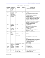
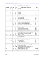
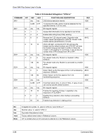
Omni 56K Plus Series User's Guide Table 4-16 Extended S-Registers "ATSn=x" COMMAND BIT DEC HEX FUNCTION AND DESCRIPTION 2 2 Speaker is ON until carrier is detected. (Default) 4 4 Speaker is always ON. 6 6 Speaker is ON after last digit is dialed out until carrier detected. 3 0 0 DSR is always ON. (Default) 8 8 According to CCITT. (see also S44.4, S41.5) 4 0 0 CD is always ON. 16 10 CD tracks presence of data carrier. (see also S38.3) (Default) 6-7 0 0 Assume DTR always On. 64 40 108.1, DTR OFF-ON transition causes dial of the default number. 128 80 108.2 Data Terminal Ready, DTR OFF causes the modem to hang up and return to command state. (Default) 192 C0 108.2+RST, DTR OFF causes the modem to hang up and reset the modem to profile 0 after DTR dropped. S23= bit dec hex Bit mapped register. 0 0 0 Command echo disabled. 1 1 Command echo enabled. (Default) 1 0 0 Tone dial. (Default) 2 2 Pulse dial. 2 0 0 Pulse dial make/break ratio = 39% / 61% (Default) 4 4 Pulse dial make/break ratio = 33% / 67% 3-5 0 0 ATX0 (See result code table) 8 8 ATX1 16 10 ATX2 24 18 ATX3 32 20 ATX4 40 28 ATX5, error control result code is enabled. (Default) 48 30 ATX6, error control result code is enabled. 56 38 ATX7, error control result code is enabled. 6 0 0 Display result code in numeric format. (see S35.7) 64 40 Display result code in verbose format. (Default) 7 0 0 Modem returns result code. (Default) 128 80 Modem does not return result code. (see also S40.1) S24= bit dec hex Bit mapped register. REF. M1* M2 M3 &S0* &S1 &C0 &C1* &D0 &D1 &D2* &D3 +105 E0 E1* T* P &P0* &P1 X0 X1 X2 X3 X4 X5* X6 X7 V0 V1* Q0* Q1 4-22 Command Sets
-
 1
1 -
2
-
3
-
4
-
5
-
6
-
7
-
8
-
9
-
10
-
11
-
12
-
13
-
14
-
15
-
16
-
17
-
18
-
19
-
20
-
21
-
22
-
23
-
24
-
25
-
26
-
27
-
28
-
29
-
30
-
31
-
32
-
33
-
34
-
35
-
36
-
37
-
38
-
39
-
40
-
41
-
42
-
43
-
44
-
 45
45 -
 46
46 -
 47
47 -
 48
48 -
 49
49 -
 50
50 -
 51
51 -
 52
52 -
 53
53 -
 54
54 -
 55
55 -
56
-
57
-
58
-
59
-
60
-
61
-
62
-
63
-
64
-
65
-
66
 |
 |