3Com 2816 SFP User Guide - Page 22
Fan Status, Summary Screen
 |
UPC - 662705480947
View all 3Com 2816 SFP manuals
Add to My Manuals
Save this manual to your list of manuals |
Page 22 highlights
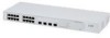
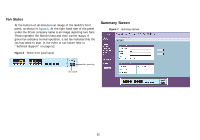
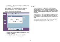
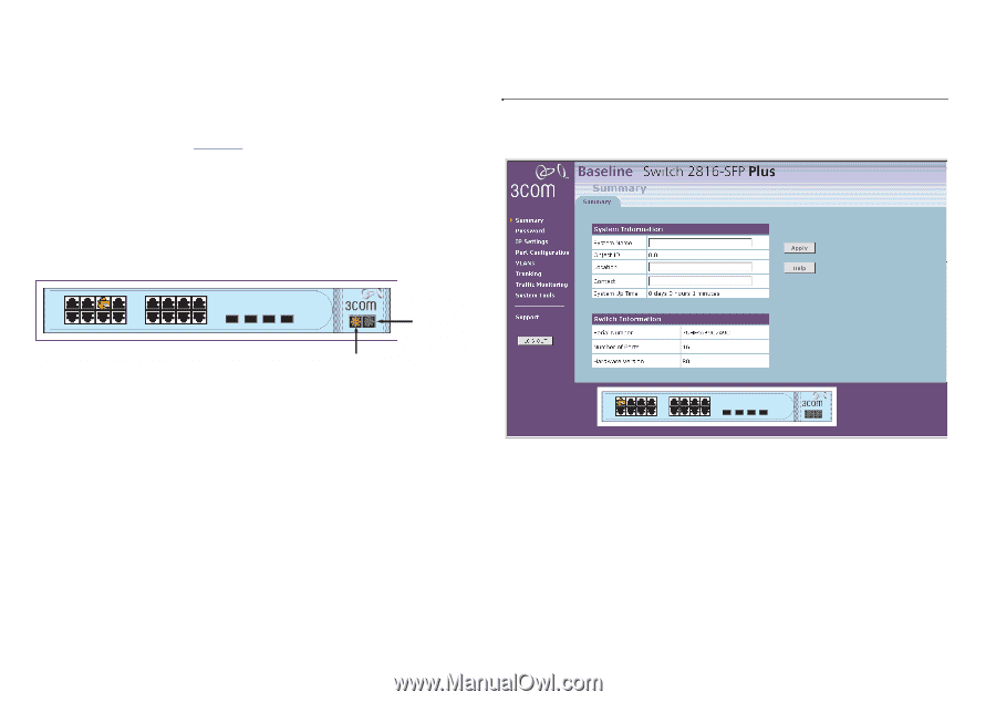
Fan Status At the bottom of all screens is an image of the Switch's front panel, as shown in Figure 6. At the right hand side of the panel under the 3Com company name is an image depicting two fans. These represent the Switch's fans and their current status. A green fan indicates normal operation, a red fan indicates that the fan has failed to start. In the event of fan failure refer to "Technical Support" on page 52. Figure 6 Switch front panel layout Summary Screen Figure 7 Summary Screen Fan operating Fan failure 22
-
 1
1 -
2
-
3
-
4
-
5
-
6
-
7
-
8
-
9
-
10
-
11
-
12
-
13
-
14
-
15
-
16
-
 17
17 -
 18
18 -
 19
19 -
 20
20 -
 21
21 -
 22
22 -
 23
23 -
 24
24 -
 25
25 -
 26
26 -
 27
27 -
28
-
29
-
30
-
31
-
32
-
33
-
34
-
35
-
36
-
37
-
38
-
39
-
40
-
41
-
42
-
43
-
44
-
45
-
46
-
47
-
48
-
49
-
50
-
51
-
52
-
53
-
54
-
55
-
56
-
57
-
58
-
59
-
60
-
61
-
62
-
63
-
64
-
65
-
66
 |
 |
22
Fan Status
At the bottom of all screens is an image of the Switch’s front
panel, as shown in
Figure 6
. At the right hand side of the panel
under the 3Com company name is an image depicting two fans.
These represent the Switch’s fans and their current status. A
green fan indicates normal operation, a red fan indicates that the
fan has failed to start. In the event of fan failure refer to
“Technical Support” on page 52.
Figure 6
Switch front panel layout
Summary Screen
Figure 7
Summary Screen
Fan failure
Fan operating