3Com 2816 SFP User Guide - Page 27
Uplink VLAN Configuration Example, In the Modify VLANs screen for Switch 1, select
 |
UPC - 662705480947
View all 3Com 2816 SFP manuals
Add to My Manuals
Save this manual to your list of manuals |
Page 27 highlights
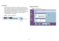
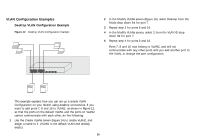
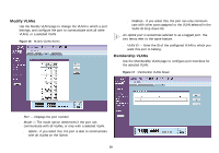
Uplink VLAN Configuration Example Figure 13 Uplink VLAN Configuration Example Endstation in VLAN 1 (Desktop) Server in VLAN 1 (Desktop) Endstation in VLAN 2 (Desktop) Switch 1 Switch 2 Port 16 in VLANs 1 and 2 (Uplink) Port 8 in VLANs 1 and 2 (Uplink) 2 In the Modify VLANs screen (Figure 16) for Switch 1, select Desktop from the Mode drop down list for the ports you want to add to VLAN2. 3 Select 2 from the VLAN ID drop down list for the ports you want to add to VLAN2. 4 Repeat steps 2 and 3 for Switch 2. 5 Select Uplink as the Mode for port 16 on Switch 1. 6 Select Uplink as the Mode for port 8 on Switch 2. 7 Connect port 16 on Switch 1 to port 8 on Switch 2. Those ports on Switch 1 that are members of VLAN2 can now communicate with those ports on Switch 2 that are members of VLAN2. Endstation in VLAN 2 (Desktop) Server in VLAN 2 (Desktop) Endstation in VLAN 1 (Desktop) This example explains how you can set up a VLAN Configuration across two Switches using Uplink connections. This enables ports that are members of the same VLAN, but which are on different switches to communicate, provided that a port on each switch is set to Uplink, and that these ports are connected. To set up the configuration shown in Figure 13, do the following: 1 Use the Create VLANs screen (Figure 14) to create VLAN2 on both Switch 1 and Switch 2, and assign the same name to it. (VLAN1 is the default VLAN and already exists.) 27
-
 1
1 -
2
-
3
-
4
-
5
-
6
-
7
-
8
-
9
-
10
-
11
-
12
-
13
-
14
-
15
-
16
-
17
-
18
-
19
-
20
-
21
-
 22
22 -
 23
23 -
 24
24 -
 25
25 -
 26
26 -
 27
27 -
 28
28 -
 29
29 -
 30
30 -
 31
31 -
 32
32 -
33
-
34
-
35
-
36
-
37
-
38
-
39
-
40
-
41
-
42
-
43
-
44
-
45
-
46
-
47
-
48
-
49
-
50
-
51
-
52
-
53
-
54
-
55
-
56
-
57
-
58
-
59
-
60
-
61
-
62
-
63
-
64
-
65
-
66
 |
 |
