Aastra OpenCom X320 User Guide - Page 42
Mounting, Mounting location, Attachment diagram, Opening, and closing OpenCom X320
 |
View all Aastra OpenCom X320 manuals
Add to My Manuals
Save this manual to your list of manuals |
Page 42 highlights
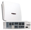
Installation Mounting 6. Tighten the Velcro fastener. 7. Replace the cover and connect the power cable to the power supply unit (see Opening and closing OpenCom X320 starting on page 27). 3.8 Mounting The device must be mounted in a suitable place. Please see the section on Mounting location starting on page 26 for details. The OpenCom X320 is attached to the wall by means of 3 screws as shown in the diagram below: Suspension (backside of device) A 266 mm B B 290 mm Mounting hole Attachment diagram Mounting hole Take the cover off the OpenCom X320 to screw in the screws for attchment point B and insert the screws through the holes provided. The OpenCom X320 will hang on the screws in attachment point A, so you must leave a space of 4 mm between the screw heads and the wall. 40
-
 1
1 -
2
-
3
-
4
-
5
-
6
-
7
-
8
-
9
-
10
-
11
-
12
-
13
-
14
-
15
-
16
-
17
-
18
-
19
-
20
-
21
-
22
-
23
-
24
-
25
-
26
-
27
-
28
-
29
-
30
-
31
-
32
-
33
-
34
-
35
-
36
-
 37
37 -
 38
38 -
 39
39 -
 40
40 -
 41
41 -
 42
42 -
 43
43 -
 44
44 -
 45
45 -
 46
46 -
 47
47 -
48
-
49
-
50
-
51
-
52
-
53
-
54
-
55
-
56
-
57
-
58
-
59
-
60
-
61
-
62
-
63
-
64
-
65
-
66
-
67
-
68
-
69
-
70
-
71
-
72
-
73
-
74
-
75
-
76
-
77
-
78
-
79
-
80
-
81
-
82
-
83
-
84
-
85
-
86
-
87
-
88
-
89
-
90
-
91
-
92
-
93
-
94
-
95
-
96
-
97
-
98
-
99
-
100
-
101
-
102
-
103
-
104
-
105
-
106
-
107
-
108
-
109
-
110
-
111
-
112
-
113
-
114
-
115
-
116
-
117
-
118
-
119
-
120
-
121
-
122
-
123
-
124
-
125
-
126
-
127
-
128
-
129
-
130
-
131
-
132
-
133
-
134
-
135
-
136
-
137
-
138
-
139
-
140
-
141
-
142
-
143
-
144
-
145
-
146
-
147
-
148
-
149
-
150
-
151
-
152
-
153
-
154
-
155
-
156
-
157
-
158
-
159
-
160
-
161
-
162
-
163
-
164
-
165
-
166
-
167
-
168
-
169
-
170
-
171
-
172
-
173
-
174
-
175
-
176
-
177
-
178
-
179
-
180
-
181
-
182
-
183
-
184
-
185
-
186
-
187
-
188
-
189
-
190
-
191
-
192
 |
 |
