Aastra OpenCom X320 User Guide - Page 65
PBX Configu, ration: Ports: Slots, Status, Mounting Interface Cards, Installing the V.24 cable
 |
View all Aastra OpenCom X320 manuals
Add to My Manuals
Save this manual to your list of manuals |
Page 65 highlights
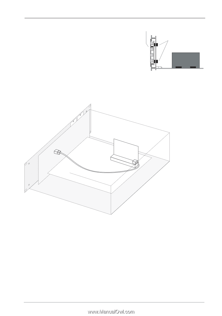
Mounting the OpenCom X320 Rack InfoCom System Installing interface cards (Example: 4. .Install the metal screen on the front panel. Each interface card type requires a matching metal screen. An overview of available metal screens can be found under Mounting Interface Cards starting on page 59. Verify the tight connection of both connectors. Tighten the fastening screws. Front Panel Connectors Interface Card 5. No connections are required for the fax function. If you want to use the V.24 function, connect the 8-pin RJ45 plug of the provided serial cable with the RJ45 socket on the card. Connect the other end of the serial cable to the front panel. For pull relief, fasten the cable with cable ties. Installing the V.24 cable 6. Close the top cover. Tighten the screws of the top cover. Switch on the OpenCom X320 Rack. You can view the interface card's status in the Web console once you have restarted OpenCom X320 Rack. To do this, call up the menu item PBX Configuration: Ports: Slots. You will see a green tick in the Status column in the table. 63
-
 1
1 -
2
-
3
-
4
-
5
-
6
-
7
-
8
-
9
-
10
-
11
-
12
-
13
-
14
-
15
-
16
-
17
-
18
-
19
-
20
-
21
-
22
-
23
-
24
-
25
-
26
-
27
-
28
-
29
-
30
-
31
-
32
-
33
-
34
-
35
-
36
-
37
-
38
-
39
-
40
-
41
-
42
-
43
-
44
-
45
-
46
-
47
-
48
-
49
-
50
-
51
-
52
-
53
-
54
-
55
-
56
-
57
-
58
-
59
-
 60
60 -
 61
61 -
 62
62 -
 63
63 -
 64
64 -
 65
65 -
 66
66 -
 67
67 -
 68
68 -
 69
69 -
 70
70 -
71
-
72
-
73
-
74
-
75
-
76
-
77
-
78
-
79
-
80
-
81
-
82
-
83
-
84
-
85
-
86
-
87
-
88
-
89
-
90
-
91
-
92
-
93
-
94
-
95
-
96
-
97
-
98
-
99
-
100
-
101
-
102
-
103
-
104
-
105
-
106
-
107
-
108
-
109
-
110
-
111
-
112
-
113
-
114
-
115
-
116
-
117
-
118
-
119
-
120
-
121
-
122
-
123
-
124
-
125
-
126
-
127
-
128
-
129
-
130
-
131
-
132
-
133
-
134
-
135
-
136
-
137
-
138
-
139
-
140
-
141
-
142
-
143
-
144
-
145
-
146
-
147
-
148
-
149
-
150
-
151
-
152
-
153
-
154
-
155
-
156
-
157
-
158
-
159
-
160
-
161
-
162
-
163
-
164
-
165
-
166
-
167
-
168
-
169
-
170
-
171
-
172
-
173
-
174
-
175
-
176
-
177
-
178
-
179
-
180
-
181
-
182
-
183
-
184
-
185
-
186
-
187
-
188
-
189
-
190
-
191
-
192
 |
 |