Acer Aspire G7710 Aspire G7710 Series User's Guide - EN - Page 34
Front panel connectors, Serial port connector (for selected models), Serial Out or Transmit Data
 |
View all Acer Aspire G7710 manuals
Add to My Manuals
Save this manual to your list of manuals |
Page 34 highlights
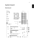
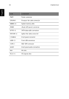
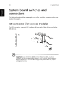
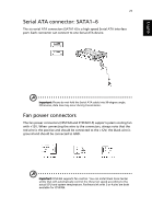
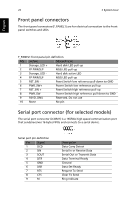
English 22 2 System tour Front panel connectors The front panel connectors (F_PANEL1) are for electrical connection to the front panel switches and LEDs. F_PANEL1 front panel pin definition PIN SIGNAL DESCRIPTION 1 Storage_LED + Hard disk LED pull-up 2 FP PWR/SLP MSG LED pull-up 3 Storage_LED - Hard disk active LED 4 FP PWR/SLP MSG LED pull-up 5 RST_SW - Reset Switch low reference pull-down to GND 6 PWR_SW+ Power Switch low reference pull-up 7 RST_SW + Reset Switch high reference pull-up 8 PWR_SW- Power Switch high reference pull-down to GND 9 RSVD_DNU Reserved. Do not use 10 None No pin Serial port connector (for selected models) The serial port connector (JCOM1) is a 16550A high speed communication port that sends/receives 16 bytes FIFOs and connects to a serial device. Serial port pin definition Pin Signal 1 DCD 2 SIN 3 SOUT 4 DTR 5 GND 6 DSR 7 RTS 8 CTS 9 RI Description Data Carry Detect Serial In or Receive Data Serial Out or Transmit Data Data Terminal Ready Ground Data Set Ready Request To Send Clear To Send Ring Indicate
-
 1
1 -
2
-
3
-
4
-
5
-
6
-
7
-
8
-
9
-
10
-
11
-
12
-
13
-
14
-
15
-
16
-
17
-
18
-
19
-
20
-
21
-
22
-
23
-
24
-
25
-
26
-
27
-
28
-
 29
29 -
 30
30 -
 31
31 -
 32
32 -
 33
33 -
 34
34 -
 35
35 -
 36
36 -
 37
37 -
 38
38 -
 39
39 -
40
-
41
-
42
-
43
-
44
-
45
-
46
-
47
-
48
-
49
-
50
-
51
-
52
-
53
-
54
-
55
-
56
-
57
-
58
-
59
-
60
-
61
-
62
-
63
-
64
-
65
-
66
-
67
-
68
-
69
-
70
-
71
-
72
-
73
-
74
-
75
-
76
-
77
-
78
-
79
-
80
-
81
-
82
-
83
-
84
-
85
-
86
-
87
-
88
-
89
-
90
-
91
-
92
-
93
-
94
-
95
-
96
-
97
-
98
-
99
-
100
-
101
-
102
 |
 |
