Acer Aspire G7710 Aspire G7710 Series User's Guide - EN - Page 71
System memory configuration guidelines, First pair: DIMM 2, DIMM 4 and DIMM 6
 |
View all Acer Aspire G7710 manuals
Add to My Manuals
Save this manual to your list of manuals |
Page 71 highlights
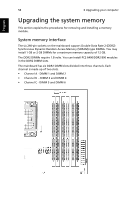
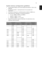
59 English System memory configuration guidelines • To ensure data integrity, use only Acer-approved modules in 1 GB or 2 GB capacities. • Use identical modules - same specification for size, speed, and organization. • In minimum configuration, the FDB should be installed in DIMM 2 slot. • Install memory pair upgrades in the following sequence: • First pair: DIMM 2, DIMM 4 and DIMM 6 • Upgrade 1: DIMM 1, 3 and 5 • Upgrade 2: DIMM 1, 2, 3, 4, 5 and 6 • Observe the population sequence illustrated in the table below when installing a memory module. DIMM 1 1 GB 1 GB 1 GB 1 GB 1 GB 2 GB 2 GB 2 GB 2 GB 2 GB Channel A DIMM 2 1 GB 1 GB 1 GB 1 GB 1 GB 1 GB 1 GB 1 GB 2 GB 2 GB 2 GB 2 GB 2 GB 2 GB 2 GB 2 GB Channel B DIMM 3 DIMM 4 1 GB 1 GB 1 GB 1 GB 1 GB 1 GB 1 GB 1 GB 1 GB 1 GB 2 GB 2 GB 2 GB 2 GB 2 GB 2 GB 2 GB 2 GB 2 GB 2 GB Channel C DIMM 5 DIMM 6 1 GB 1 GB 1 GB 1 GB 1 GB 1 GB 1 GB 2 GB 2 GB 2 GB 2 GB 2 GB 2 GB 2 GB
-
 1
1 -
2
-
3
-
4
-
5
-
6
-
7
-
8
-
9
-
10
-
11
-
12
-
13
-
14
-
15
-
16
-
17
-
18
-
19
-
20
-
21
-
22
-
23
-
24
-
25
-
26
-
27
-
28
-
29
-
30
-
31
-
32
-
33
-
34
-
35
-
36
-
37
-
38
-
39
-
40
-
41
-
42
-
43
-
44
-
45
-
46
-
47
-
48
-
49
-
50
-
51
-
52
-
53
-
54
-
55
-
56
-
57
-
58
-
59
-
60
-
61
-
62
-
63
-
64
-
65
-
 66
66 -
 67
67 -
 68
68 -
 69
69 -
 70
70 -
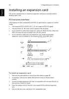
 71
71 -
 72
72 -
 73
73 -
 74
74 -
 75
75 -
 76
76 -
77
-
78
-
79
-
80
-
81
-
82
-
83
-
84
-
85
-
86
-
87
-
88
-
89
-
90
-
91
-
92
-
93
-
94
-
95
-
96
-
97
-
98
-
99
-
100
-
101
-
102
 |
 |