Acer G330 Altos G330 User's Guide - Page 48
diagonally opposite pattern, then tighten them completely
 |
UPC - 750519177044
View all Acer G330 manuals
Add to My Manuals
Save this manual to your list of manuals |
Page 48 highlights
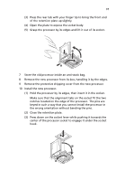
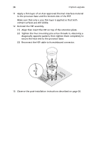
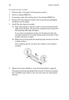
38 3 System upgrade 11 Apply a thin layer of an Acer-approved thermal interface material to the processor base and the bottom side of the HSF. Make sure that only a very thin layer is applied so that both contact surfaces are still visible. 12 Reinstall the HSF assembly. (1) Align then insert the HSF on top of the retention plate. (2) Tighten the four mounting pins a few threads in, observing a diagonally opposite pattern, then tighten them completely to secure the heat sink to the processor base. (3) Reconnect the HSF cable to its mainboard connector. 13 Observe the post-installation instructions described on page 26.
-
 1
1 -
2
-
3
-
4
-
5
-
6
-
7
-
8
-
9
-
10
-
11
-
12
-
13
-
14
-
15
-
16
-
17
-
18
-
19
-
20
-
21
-
22
-
23
-
24
-
25
-
26
-
27
-
28
-
29
-
30
-
31
-
32
-
33
-
34
-
35
-
36
-
37
-
38
-
39
-
40
-
41
-
42
-
 43
43 -
 44
44 -
 45
45 -
 46
46 -
 47
47 -
 48
48 -
 49
49 -
 50
50 -
 51
51 -
 52
52 -
 53
53 -
54
-
55
-
56
-
57
-
58
-
59
-
60
-
61
-
62
-
63
-
64
-
65
-
66
-
67
-
68
-
69
-
70
-
71
-
72
-
73
-
74
-
75
-
76
-
77
-
78
-
79
-
80
-
81
-
82
-
83
-
84
-
85
-
86
-
87
-
88
-
89
-
90
-
91
-
92
-
93
-
94
-
95
-
96
-
97
-
98
-
99
-
100
-
101
-
102
-
103
-
104
-
105
-
106
-
107
-
108
-
109
-
110
-
111
-
112
-
113
-
114
-
115
-
116
-
117
-
118
-
119
-
120
-
121
-
122
-
123
-
124
 |
 |

3 System upgrade
38
11
Apply a thin layer of an Acer-approved thermal interface material
to the processor base and the bottom side of the HSF.
Make sure that only a
very thin layer
is applied so that both
contact surfaces are still visible.
12
Reinstall the HSF assembly.
(1)
Align then insert the HSF on top of the retention plate.
(2)
Tighten the four mounting pins a few threads in, observing a
diagonally opposite pattern, then tighten them completely to
secure the heat sink to the processor base.
(3)
Reconnect the HSF cable to its mainboard connector.
13
Observe the post-installation instructions described on page 26.