Alcatel OS6602-24 Getting Started Guide - Page 31
Assigning Slot Numbers, Note., SEL Button Location
 |
View all Alcatel OS6602-24 manuals
Add to My Manuals
Save this manual to your list of manuals |
Page 31 highlights
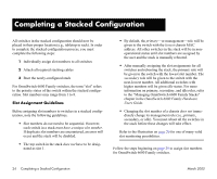
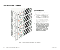
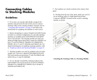
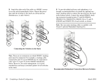
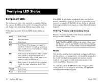
Assigning Slot Numbers 1 Power on a single switch in the stack. Do not power on any additional switches in the stack at this time. The slot number is displayed by the slot indicator LED located on the left side of the chassis front panel (refer to "OmniSwitch 6600 Status LEDs" on page 67 for more information). Because the switch's default slot number is 8, the slot indicator LED displays "8" when the switch is first booted. 2 To change the slot number, gently insert a pointed item, such as the open, pointed end of a paper clip, into the small hole (labeled SEL) below the slot number LED on the switch's front panel. The LED display will begin to flash. You can manually change the slot number as long as the LED continues to flash. Note. The LED may also advance by one number when the SEL button is initially pressed. 3 Change the slot number by gently pressing the pointed item into the SEL hole again. Each time the SEL button is pressed, the LED display increases or decreases in increments of one. OmniSwitch 6624 OK1 OK2 PS1 PS2 PRI TEM SEC FAN SEL 25 26 1 28 3 30 5 34 9 32 7 10 8 12 TM CONSOLE 6 4 2 OK1 OK2 PS1 PS2 PRI TEMP SEC FAN SEL 16 14 SEL Button Location 4 Continue pressing the SEL button until you reach the number that is one increment higher than the desired slot number, then hold in the SEL button until the LED decreases one increment (to your desired number) and stops flashing. 5 Power off the switch. 6 Repeat steps 1 through 5 for all switches in the stack. 7 Continue to "Connecting Cables to Stacking Modules" on page 27. For a diagram showing one of many valid slot numbering examples, refer to page 26. March 2005 Completing a Stacked Configuration 25
-
 1
1 -
2
-
3
-
4
-
5
-
6
-
7
-
8
-
9
-
10
-
11
-
12
-
13
-
14
-
15
-
16
-
17
-
18
-
19
-
20
-
21
-
22
-
23
-
24
-
25
-
 26
26 -
 27
27 -
 28
28 -
 29
29 -
 30
30 -
 31
31 -
 32
32 -
 33
33 -
 34
34 -
 35
35 -
 36
36 -
37
-
38
-
39
-
40
-
41
-
42
-
43
-
44
-
45
-
46
-
47
-
48
-
49
-
50
-
51
-
52
-
53
-
54
-
55
-
56
-
57
-
58
-
59
-
60
-
61
-
62
-
63
-
64
-
65
-
66
-
67
-
68
-
69
-
70
-
71
-
72
-
73
-
74
-
75
-
76
 |
 |
