Alcatel OS6602-24 Getting Started Guide - Page 33
Connecting Cables to Stacking Modules, Guidelines
 |
View all Alcatel OS6602-24 manuals
Add to My Manuals
Save this manual to your list of manuals |
Page 33 highlights
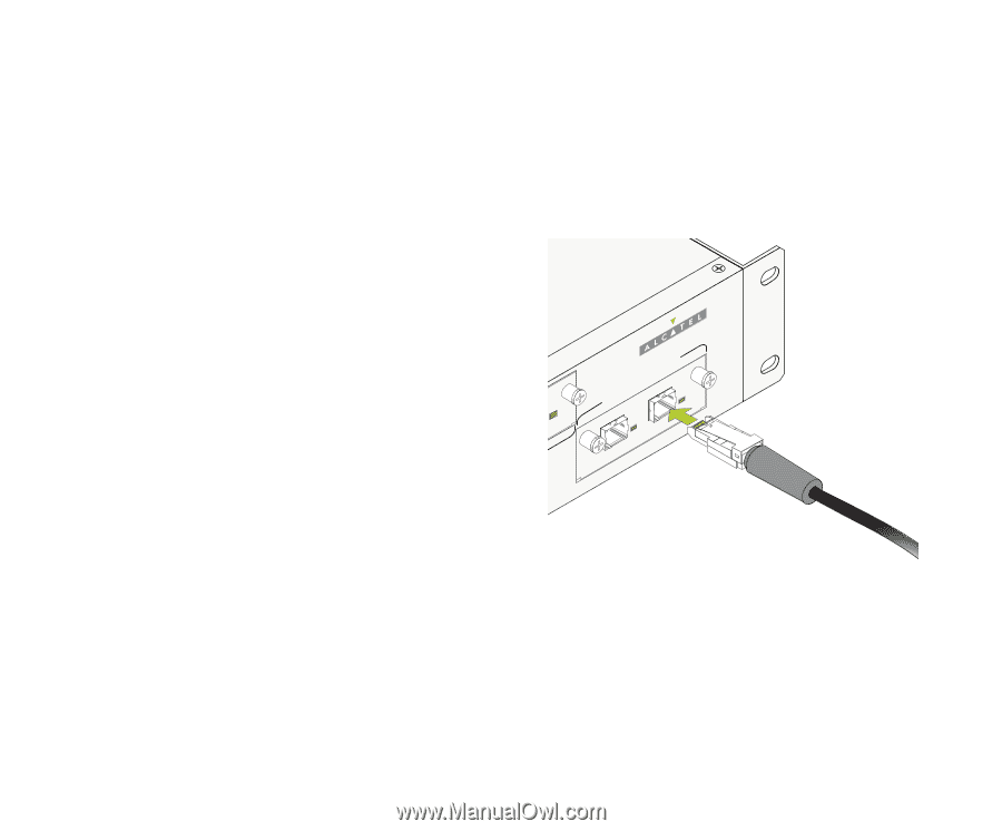
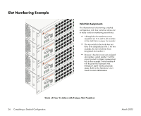
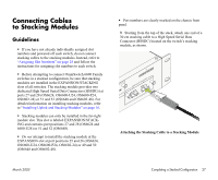
Connecting Cables to Stacking Modules Guidelines • If you have not already individually assigned slot numbers and powered off each switch, do not connect stacking cables to the stacking modules. Instead, refer to "Assigning Slot Numbers" on page 25 and follow the instructions for assigning slot numbers to each switch. • Before attempting to connect OmniSwitch 6600 Family switches in a stacked configuration, be sure that stacking modules are installed in the EXPANSION/STACKING slots of all switches. The stacking module provides two dedicated High Speed Serial Data Connectors (HSSDCs) at ports 27 and 28 (OS6624, OS6600-U24, OS6600-P24, OS6602-24) or 51 and 52 (OS6648 and OS6602-48). For detailed information on installing stacking modules, refer to "Installing Uplink and Stacking Modules" on page 16. • Stacking modules can only be installed in the far-right module slot. This slot is labeled EXPANSION/STACKING and contains port positions 27 and 28 (OS6624 and 6600-U24) or 51 and 52 (OS6648). • Do not attempt to install the stacking module at the EXPANSION slot at port positions 25 and 26 (OS6624, OS6600-U24, OS6600-P24, OS6602-24) or 49 and 50 (OS6648 and OS6602-48). • Port numbers are clearly marked on the chassis front panel. 1 Starting from the top of the stack, attach one end of a 30 cm stacking cable to a High Speed Serial Data Connector (HSSDC) located on the switch's stacking module, as shown. E5X1PANSION/STAC5 2KINLGINK/ACT LINK/ACT Attaching the Stacking Cable to a Stacking Module March 2005 Completing a Stacked Configuration 27
-
 1
1 -
2
-
3
-
4
-
5
-
6
-
7
-
8
-
9
-
10
-
11
-
12
-
13
-
14
-
15
-
16
-
17
-
18
-
19
-
20
-
21
-
22
-
23
-
24
-
25
-
26
-
27
-
 28
28 -
 29
29 -
 30
30 -
 31
31 -
 32
32 -
 33
33 -
 34
34 -
 35
35 -
 36
36 -
 37
37 -
 38
38 -
39
-
40
-
41
-
42
-
43
-
44
-
45
-
46
-
47
-
48
-
49
-
50
-
51
-
52
-
53
-
54
-
55
-
56
-
57
-
58
-
59
-
60
-
61
-
62
-
63
-
64
-
65
-
66
-
67
-
68
-
69
-
70
-
71
-
72
-
73
-
74
-
75
-
76
 |
 |