Alcatel OS6602-24 Getting Started Guide - Page 35
Booting the Stack, Booting Stand-Alone Switches, Important., Automatic Software Synchronization.
 |
View all Alcatel OS6602-24 manuals
Add to My Manuals
Save this manual to your list of manuals |
Page 35 highlights
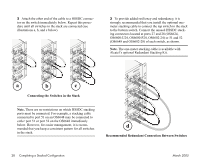
4 Now that all switches in the stack are connected, continue to "Booting the Stack" on page 29. Booting the Stack In order for the switches in the stack to operate using their newly-assigned slot numbers, all switches in the stack must be manually booted. To manually boot the stack, follow the steps below. 1 Power on all switches by moving the on/off switch for each switch to the on ( | ) position. Important. Be sure to power on all switches in the stack in rapid succession. If you do not power up all switches within approximately three seconds, switches may take unintended stack management roles. After the stack is completely booted, all switches in the stack will operate with the user-assigned slot numbers. Automatic Software Synchronization. In order to ensure effective redundancy within a stacked configuration, the primary switch will automatically distribute its system and configuration software to all switches in the stack as the virtual chassis boots. 2 If back up power supplies are installed in one or more switches in the stack, power on all back up power supplies at this time. March 2005 3 After you have booted the stack and powered on all back up power supplies (if applicable), continue to "Verifying LED Status" on page 30. Booting Stand-Alone Switches 1 To boot a single, stand-alone switch, simply move the on/off switch for each switch to the on ( | ) position. This switch is located on the rear panel of the switch, next to the power cord socket. Note. Because the switch's default slot number is 8, the slot indicator LED displays "8" when the switch is first booted. 2 If the stand-alone switch has a back up power supply installed, you may power on this unit as well. Move the on/off switch for the back up power supply to the on ( | ) position. 3 After you have booted the stand-alone switch and powered on the back up power supply (if applicable), continue to "Verifying LED Status" on page 30. This section provides information on LED states and switch status both during and after the boot process. Completing a Stacked Configuration 29
-
 1
1 -
2
-
3
-
4
-
5
-
6
-
7
-
8
-
9
-
10
-
11
-
12
-
13
-
14
-
15
-
16
-
17
-
18
-
19
-
20
-
21
-
22
-
23
-
24
-
25
-
26
-
27
-
28
-
29
-
 30
30 -
 31
31 -
 32
32 -
 33
33 -
 34
34 -
 35
35 -
 36
36 -
 37
37 -
 38
38 -
 39
39 -
 40
40 -
41
-
42
-
43
-
44
-
45
-
46
-
47
-
48
-
49
-
50
-
51
-
52
-
53
-
54
-
55
-
56
-
57
-
58
-
59
-
60
-
61
-
62
-
63
-
64
-
65
-
66
-
67
-
68
-
69
-
70
-
71
-
72
-
73
-
74
-
75
-
76
 |
 |
