Alpine D900 Owners Manual - Page 48
Performing Time Correction Manually TCR, Swithing the Phase, X-OVER Adjustment
 |
UPC - 793276200310
View all Alpine D900 manuals
Add to My Manuals
Save this manual to your list of manuals |
Page 48 highlights
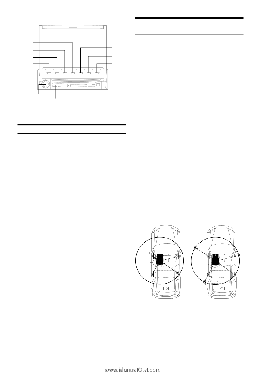
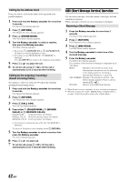
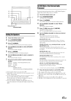
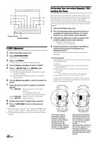
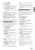
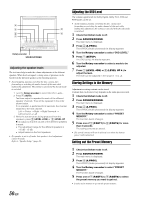
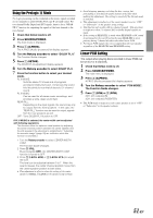
4 3 5 2 6 1 7 Rotary encoder SOURCE/POWER X-OVER Adjustment 1 Check that defeat mode is off. 2 Press SOURCE/POWER. The main menu is displayed. 3 Press 4 (A.PROC). A.PROC (Audio processor) list display appears. 4 Turn the Rotary encoder to select "X-OVER." 5 Press 1 (SETUP L/R) or 2 (SETUP L+R). X-OVER adjustment display appears. L/R: Different adjustment values can be set for the left and right channels. L+R: Sets the same adjustment values for the left and right channels. 6 Turn the Rotary encoder to select the speaker to be set. 7 Press the function button to adjust the selected speaker. FREQ. ;DN/UP:: Adjust the H.P.F. or L.P.F. cutoff frequency. The adjustable bands differ according to the channel (speaker). SLOPE ;DN/UP:: Adjust the H.P.F. or L.P.F. slope. LEVEL ;DN/UP:: Adjust the level. 8 Repeat steps 6 and 7 to adjust other channels. 9 Press 7 (RETURN) to return to the previous display. • When the speaker is set to the "OFF" mode, the X-OVER for that speaker is ineffective. Refer to "Setting the Speakers" (page 45). • Check the playback frequencies of the connected speakers before adjusting. 46-EN Performing Time Correction Manually (TCR)/ Swithing the Phase Because of the particular conditions inside the vehicle, there can be major differences in the distances between the various speakers and the listening position. It is possible to calculate the optimum correction values and eliminate the time error at the listening position yourself using this function. You can also use this function to switch the phase. 1 Check that Defeat mode is off. 2 Sit in the listening position (the driver's seat, for example) and measure the distance (in meters) between your head and the various speakers. 3 Calculate the difference in distance between the farthest speaker and the other speakers. L = (distance of farthest speaker) - (distance of other speakers) 4 Divide the distances calculated for the different speakers by the speed of sound (343 m/s temperature 20°C). This value is the time correction value for the various speakers. Concrete examples Calculating the time correction value for the front left speaker on the diagram below. Conditions: Distance between farthest speaker and listening position: 2.25 m (88-3/4") Distance between front left speaker and listening position: 0.5 m (20") Calculation: L = 2.25 m (88-3/4") - 0.5 m (20")= 1.75 m (68-3/4") Compensation time = 1.75 ÷ 343 x 1000 = 5.1 (ms) In other words, setting the time correction value for the front left speaker to 5.1 (ms) sets a virtual distance matching the distance to the farthest speaker. 0.5m 2.25m 5.1ms The sound is uneven because the distance between the listening position and the different speakers is different. The difference in the distance between the front left and rear right speakers is 1.75 meters (68-3/4"). Time correction eliminates the difference between the time required for the sound from the different speakers to reach the listening position. Setting the time correction of the front left speaker to 5.1 ms makes it possible to coordinate the distance from the listening position to the speaker.
-
 1
1 -
2
-
3
-
4
-
5
-
6
-
7
-
8
-
9
-
10
-
11
-
12
-
13
-
14
-
15
-
16
-
17
-
18
-
19
-
20
-
21
-
22
-
23
-
24
-
25
-
26
-
27
-
28
-
29
-
30
-
31
-
32
-
33
-
34
-
35
-
36
-
37
-
38
-
39
-
40
-
41
-
42
-
 43
43 -
 44
44 -
 45
45 -
 46
46 -
 47
47 -
 48
48 -
 49
49 -
 50
50 -
 51
51 -
 52
52 -
 53
53 -
54
-
55
-
56
-
57
-
58
-
59
-
60
-
61
-
62
-
63
-
64
-
65
-
66
-
67
-
68
-
69
-
70
-
71
-
72
-
73
-
74
-
75
-
76
-
77
-
78
-
79
-
80
-
81
-
82
-
83
 |
 |