Apple IMAC Service Source - Page 160
No Power Symptom Charts, fashion, the CPU may overheat and become damaged.
 |
UPC - 067540444435
View all Apple IMAC manuals
Add to My Manuals
Save this manual to your list of manuals |
Page 160 highlights
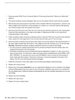
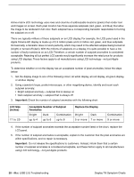
11. Remove the bottom housing. Check that all the cables on the logic board are securely connected. Pay special attention to the video connector. Power on the unit again. If you still have no power, go on to the next step. Warning: Whenever the bottom housing is opened for service, you must do two things: • You must clean the original thermal film from the surfaces joining the thermal interface layer and reapply thermal paste to the thermal pipe. • The bottom housing has four torx screws that must be tightened to at least 17 in.-lbs. If you do not have a torque driver, you will have to make sure these screws are tightened by hand FIRMLY, BUT NOT FORCIBLY. Or, purchase the service tool (076-0899) in order to ensure the thermal pipe is firmly mated with the top base. If the bottom housing is not securely attached to the base in this fashion, the CPU may overheat and become damaged. 12. Check power supply output. Disconnect the power supply cable from the logic board. Measure power at the power supply connector by touching the black probe to the ground pin, and using the red probe to measure power at the pins indicated in the graphic below. Did you measure +12v at each point? If yes, replace the logic board. If no, replace the power supply. 13. Replace the inverter board. 14. Replace the neck assembly. No Power Symptom Charts iMac (USB 2.0) Troubleshooting - 15
-
 1
1 -
2
-
3
-
4
-
5
-
6
-
7
-
8
-
9
-
10
-
11
-
12
-
13
-
14
-
15
-
16
-
17
-
18
-
19
-
20
-
21
-
22
-
23
-
24
-
25
-
26
-
27
-
28
-
29
-
30
-
31
-
32
-
33
-
34
-
35
-
36
-
37
-
38
-
39
-
40
-
41
-
42
-
43
-
44
-
45
-
46
-
47
-
48
-
49
-
50
-
51
-
52
-
53
-
54
-
55
-
56
-
57
-
58
-
59
-
60
-
61
-
62
-
63
-
64
-
65
-
66
-
67
-
68
-
69
-
70
-
71
-
72
-
73
-
74
-
75
-
76
-
77
-
78
-
79
-
80
-
81
-
82
-
83
-
84
-
85
-
86
-
87
-
88
-
89
-
90
-
91
-
92
-
93
-
94
-
95
-
96
-
97
-
98
-
99
-
100
-
101
-
102
-
103
-
104
-
105
-
106
-
107
-
108
-
109
-
110
-
111
-
112
-
113
-
114
-
115
-
116
-
117
-
118
-
119
-
120
-
121
-
122
-
123
-
124
-
125
-
126
-
127
-
128
-
129
-
130
-
131
-
132
-
133
-
134
-
135
-
136
-
137
-
138
-
139
-
140
-
141
-
142
-
143
-
144
-
145
-
146
-
147
-
148
-
149
-
150
-
151
-
152
-
153
-
154
-
 155
155 -
 156
156 -
 157
157 -
 158
158 -
 159
159 -
 160
160 -
 161
161 -
 162
162 -
 163
163 -
 164
164 -
 165
165 -
166
-
167
-
168
-
169
-
170
-
171
-
172
-
173
-
174
-
175
-
176
-
177
-
178
-
179
-
180
-
181
-
182
-
183
-
184
-
185
-
186
-
187
-
188
-
189
-
190
-
191
-
192
-
193
-
194
-
195
-
196
-
197
-
198
-
199
-
200
 |
 |
