Asus A7V8X A7V8X User Manual - Page 23
compatible UARTs, a Standard Infrared SIR, a Smart Card - x drivers
 |
View all Asus A7V8X manuals
Add to My Manuals
Save this manual to your list of manuals |
Page 23 highlights
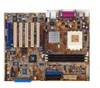
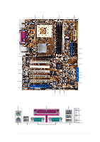
9 ASUS ASIC. This chip performs multiple system functions that include hardware and system voltage monitoring among others. 10 RAID IDE connector. This one-channel connector supports Ultra ATA133/100/66 hard disk drivers in RAID 0 or RAID 1 configurations. (on SATA model only) 11 SATA connectors. This connector accomodates the provided Serial ATA cable. One side of the connector is slotted to prevent incorrect insertion of the cable. The Serial ATA is an evolutionary replacement for the Parallel ATA. (on SATA model only) 12 Flash ROM. This 4Mb firmware contains the programmable BIOS program. 13 SATA controller. The Promise controller supports one ATA133 channel and two Serial ATA connectors. (on SATA model only) 14 Standby power LED. This LED lights up if there is a standby power on the motherboard. This LED acts as a reminder to turn off the system power before plugging or unplugging devices. 15 Super I/O controller. This Low Pin Count (LPC) interface provides the commonly used Super I/O functionality. The chipset supports a high-performance floppy disk controller for a 360K/720K/1.44M/ 2.88M floppy disk drive, a multi-mode parallel port, two standard compatible UARTs, a Standard Infrared (SIR), a Smart Card Reader and a Flash ROM interface. 16 IEEE 1394 connectors. This connectors accomodate the bundled two (2) IEEE 1394 cables. (on 1394 model only) 17 IEEE 1394 controller. This high speed serial bus provides enhanced PC connectivity for Audio and Video, high-speed peripheral devices for storage and other portable devices. (on 1394 model only) 18 PCI slots. These six 32-bit PCI 2.2 expansion slots support bus master PCI cards like SCSI or LAN cards with 133MB/s maximum throughput. (Note: The ASUS BlueMagic PCI slot works as a normal PCI slot and it is also compatible with the ASUS proprietary wireless card - Spacelink B&W) 19 Audio CODEC . The Realtek ALC650 is an AC'97 compliant audio CODEC for PC multimedia systems. (on audio models only) ASUS A7V8X motherboard user guide 1-9
-
 1
1 -
2
-
3
-
4
-
5
-
6
-
7
-
8
-
9
-
10
-
11
-
12
-
13
-
14
-
15
-
16
-
17
-
 18
18 -
 19
19 -
 20
20 -
 21
21 -
 22
22 -
 23
23 -
 24
24 -
 25
25 -
 26
26 -
 27
27 -
 28
28 -
29
-
30
-
31
-
32
-
33
-
34
-
35
-
36
-
37
-
38
-
39
-
40
-
41
-
42
-
43
-
44
-
45
-
46
-
47
-
48
-
49
-
50
-
51
-
52
-
53
-
54
-
55
-
56
-
57
-
58
-
59
-
60
-
61
-
62
-
63
-
64
-
65
-
66
-
67
-
68
-
69
-
70
-
71
-
72
-
73
-
74
-
75
-
76
-
77
-
78
-
79
-
80
-
81
-
82
-
83
-
84
-
85
-
86
-
87
-
88
-
89
-
90
-
91
-
92
-
93
-
94
-
95
-
96
-
97
-
98
-
99
-
100
-
101
-
102
-
103
-
104
-
105
-
106
-
107
-
108
-
109
-
110
-
111
-
112
-
113
-
114
-
115
-
116
-
117
-
118
-
119
-
120
-
121
-
122
-
123
-
124
-
125
-
126
-
127
-
128
-
129
-
130
-
131
-
132
-
133
-
134
-
135
-
136
-
137
-
138
-
139
-
140
-
141
-
142
 |
 |