Asus A7V8X A7V8X User Manual - Page 42
Hardware information, WPCI_USB Setting 6-pin WPCI_USB1, Clear RTC RAM CLRTC1 - enter bios
 |
View all Asus A7V8X manuals
Add to My Manuals
Save this manual to your list of manuals |
Page 42 highlights
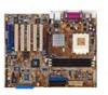
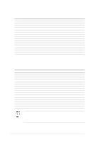
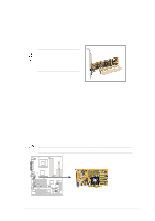
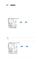
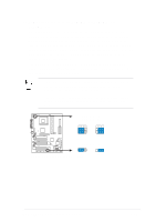
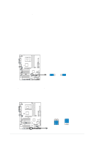
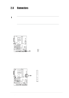
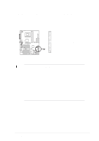
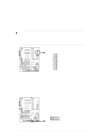
4. Clear RTC RAM (CLRTC1) These jumpers allow you to clear the Real Time Clock (RTC) RAM in CMOS. You can clear the CMOS memory of date, time, and system setup parameters by erasing the CMOS RTC RAM data. The RAM data in CMOS is powered by the onboard button cell battery. To erase the RTC RAM: 1. Turn OFF the computer and unplug the power cord. 2. Remove the battery. 3. Short the jumper by replacing the jumper cap and removing it after 3 seconds. 4. Re-install the battery. 5. Plug the power cord and turn ON the computer. 6. Hold down the key during the boot process and enter BIOS setup to re-enter data. ® A7V8X A7V8X Clear RTC RAM CLRTC1 12 23 Clear CMOS Normal (Default) 5. WPCI_USB Setting (6-pin WPCI_USB1) This jumper connects one set of USB signal to PCI slot 6 to support ASUS wireless card. Since USB signals are used by some reserved pins of PCI slot and to ensure the compatibility of the other PCI cards, it should be kept at default setting except when ASUS wireless card is used. WPCI_USB1 ® A7V8X 2-16 A7V8X WPCI_USB Setting 4 3 2 1 Wireless PCI_USB 6 5 4 3 Original PCI reserved pin (Default) Chapter 2: Hardware information
-
 1
1 -
2
-
3
-
4
-
5
-
6
-
7
-
8
-
9
-
10
-
11
-
12
-
13
-
14
-
15
-
16
-
17
-
18
-
19
-
20
-
21
-
22
-
23
-
24
-
25
-
26
-
27
-
28
-
29
-
30
-
31
-
32
-
33
-
34
-
35
-
36
-
 37
37 -
 38
38 -
 39
39 -
 40
40 -
 41
41 -
 42
42 -
 43
43 -
 44
44 -
 45
45 -
 46
46 -
 47
47 -
48
-
49
-
50
-
51
-
52
-
53
-
54
-
55
-
56
-
57
-
58
-
59
-
60
-
61
-
62
-
63
-
64
-
65
-
66
-
67
-
68
-
69
-
70
-
71
-
72
-
73
-
74
-
75
-
76
-
77
-
78
-
79
-
80
-
81
-
82
-
83
-
84
-
85
-
86
-
87
-
88
-
89
-
90
-
91
-
92
-
93
-
94
-
95
-
96
-
97
-
98
-
99
-
100
-
101
-
102
-
103
-
104
-
105
-
106
-
107
-
108
-
109
-
110
-
111
-
112
-
113
-
114
-
115
-
116
-
117
-
118
-
119
-
120
-
121
-
122
-
123
-
124
-
125
-
126
-
127
-
128
-
129
-
130
-
131
-
132
-
133
-
134
-
135
-
136
-
137
-
138
-
139
-
140
-
141
-
142
 |
 |