Asus AP3000 Hardware Reference - Page 22
Install Retention, Mechanism, Brace Bars, Mechanisms
 |
View all Asus AP3000 manuals
Add to My Manuals
Save this manual to your list of manuals |
Page 22 highlights
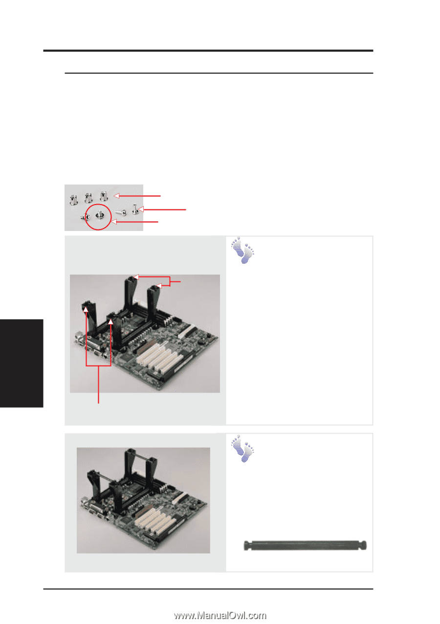
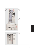
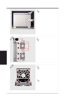
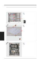
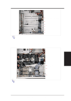
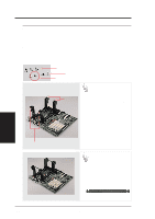
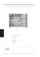
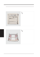
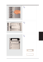
IV. Hardware Setup • 4-4. Central Processing Unit (CPU) The motherboard has two connectors for processor retention modules. One retention module can have one Xeon processor installed. Before installing the CPU, secure the motherboard on the rubber pad and metal baseboard. (See p. 20.) When only one processor is used, the other Slot 2 connector must be terminated with the provided front side bus termination module. For memory installation, refer to the motherboard User's Manual. Single Dot Captive Nut Long Screw (aligned with spacers) Short Screw Two Dots Install Retention Mechanisms For the retention mechanism, there is a left and a right side. The left side has a single dot and the right side has two dots (when holding the motherboard with the ATX connectors to the left). Place the retention mechanisms' holes over the screws and the Slot2. Screw four captive nuts onto the screws as circled in the picture on the right. Do not place the other captive nuts yet. Install Retention Mechanism Brace Bars Place the retention mechanism brace bar into the groove on the top of the retention mechanism as shown. Retention Mechanism Brace Bar IV. Hardware Setup CPU 22 AP 3000 Hardware Reference Guide
-
 1
1 -
2
-
3
-
4
-
5
-
6
-
7
-
8
-
9
-
10
-
11
-
12
-
13
-
14
-
15
-
16
-
 17
17 -
 18
18 -
 19
19 -
 20
20 -
 21
21 -
 22
22 -
 23
23 -
 24
24 -
 25
25 -
 26
26 -
 27
27 -
28
-
29
-
30
-
31
-
32
-
33
-
34
-
35
-
36
-
37
-
38
-
39
-
40
-
41
-
42
 |
 |