Asus AP3000 Hardware Reference - Page 24
Chassis Intrusion Connector
 |
View all Asus AP3000 manuals
Add to My Manuals
Save this manual to your list of manuals |
Page 24 highlights
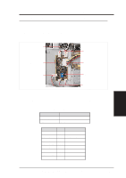
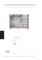
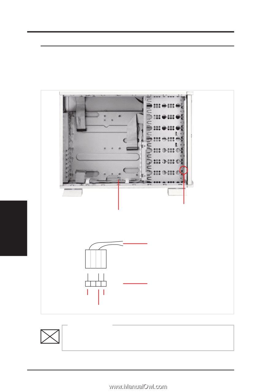
IV. Hardware Setup • 4-5. Chassis Intrusion Switch The chassis provides a micro toggle switch that must be connected to the motherboard for the chassis intrusion detection to work. The motherboard will signal the ASMA software when the side panel is opened. The connection diagram is given here. IV. Hardware Setup Chassis Intrusion Switch Cable Chassis Intrusion Switches (one on each side) from the two Chassis Intrusion Switches +5VSB GND Chasis Signal Motherboard's Chassis Intrusion Connector IMPORTANT To prevent misconnection, one pin is removed from the motherboard's chassis intrusion connector. 24 AP 3000 Hardware Reference Guide
-
 1
1 -
2
-
3
-
4
-
5
-
6
-
7
-
8
-
9
-
10
-
11
-
12
-
13
-
14
-
15
-
16
-
17
-
18
-
 19
19 -
 20
20 -
 21
21 -
 22
22 -
 23
23 -
 24
24 -
 25
25 -
 26
26 -
 27
27 -
 28
28 -
 29
29 -
30
-
31
-
32
-
33
-
34
-
35
-
36
-
37
-
38
-
39
-
40
-
41
-
42
 |
 |
24
IV. Hardware Setup
IV. Hardware Setup
AP 3000 Hardware Reference Guide
• 4-5. Chassis Intrusion Switch
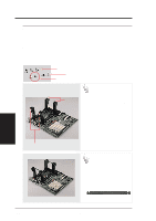
IMPORTANT
Chassis Intrusion Switches
(one on each side)
Cable
The chassis provides a micro toggle switch that must be connected to
the motherboard for the chassis intrusion detection to work. The moth-
erboard will signal the ASMA software when the side panel is opened.
The connection diagram is given here.
Chassis Intrusion Switch
To prevent misconnection, one pin is removed from the
motherboard’s chassis intrusion connector.
Motherboard’s
Chassis Intrusion Connector
from the two Chassis
Intrusion Switches
+5VSB
Chasis Signal
GND