Asus KN97 User Manual - Page 13
ASUS KN97-X User's Manual, Jumpers, Expansion Slots, Connectors, ISA NOTE, PCI NOTE
 |
View all Asus KN97 manuals
Add to My Manuals
Save this manual to your list of manuals |
Page 13 highlights
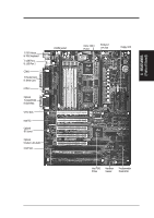
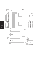
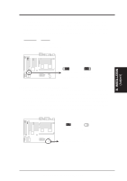
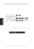
III. INSTALLATION (Map of Board) III. INSTALLATION Jumpers 1) IOEN 2) BBLKW 3) AUDIO (optional) 4) VOLADJ (optional) 5) RTCLR 6) BATTERY TEST 7) FS0, FS1 8) BF0, BF1, BF2, BF3 p. 15 Multi-I/O Selection (Enable/Disable) p. 15 Flash ROM Boot Block Program (Disable/Enable) p. 16 Onboard Audio (Disable/Enable) p. 16 Digital Volume Level Adjustment (Up/Down) p. 17 Real Time Clock RAM (Operation/Clear Data) p. 17 Battery Test Lead (Operation/Test Mode) p. 18 CPU External Clock (BUS) Frequency Selection p. 18 CPU:BUS Frequency Ratio Expansion Slots 1) System Memory 2) SIMM Sockets 3) DIMM Sockets 2) Pentium II CPU Slot 3) ISA Slots 4) PCI Slots p. 19 System Memory Support p. 20 SIMM Memory Module Support p. 21 DIMM Memory Module Support p. 22 Central Processing Unit (CPU) Cartridge Support p. 24 16-bit ISA Bus Expansion Slots* p. 24 32-bit PCI Bus Expansion Slots* Connectors 1) PS2KEYBOARD 2) PS2MOUSE 3) PRINTER 4) COM1, COM2 5) AUDIO (optional) 6) GAME (optional) 7) USB 8) FLOPPY 9) FANPWR1, 2, 3 10) CHASSIS 11) IDE1, IDE2 12) IDELED 13) PWR LED (PANEL) 14) SMI (PANEL) 15) PWR SW (CON1) 16) RESET (PANEL) 17) KEYLOCK (PANEL) 18) SPEAKER (PANEL) 19) IR 20) ATXPWR p. 26 PS/2 Keyboard Connector (6-pin Female) p. 26 PS/2 Mouse Connector (6-pin Female) p. 27 Parallel (Printer) Port Connector (25-pin Female) p. 27 Serial Port COM1 & COM2 (Two 9-pin Female) p. 27 Audio Port -Line Out, Line In, Mic (Three 1/8" Female) p. 28 Joystick/Midi Connector (15-pin Female) p. 28 Universal Serial BUS Ports 1 & 2 (Two 4-pin Female) p. 28 Floppy Drive Connector (34-pin Block) p. 29 Chassis, CPU, Power Supply Fan Power (3-pin Block) p. 29 Chassis Open Alarm Lead (3-pin Block) p. 30 Primary / Secondary IDE Connector (40-pin Blocks) p. 30 IDE LED Activity Light p. 31 System Power LED (2-pins) p. 31 SMI Switch Lead (2-pins) p. 31 ATX Power & Soft-Off Switch Lead (2-pins) p. 31 Reset Switch Lead (2-pins) p. 31 Power LED (3-pins) & Keyboard Lock Switch (2-pins) p. 31 Speaker Output Connector (4-pins) p. 32 Infrared Port Module Connector p. 32 Motherboard Power Connector (20-pin Block) *ISA NOTE: The onboard hardware monitor uses the address 290H so legacy ISA cards must not use this address or else conflicts will occur. *PCI NOTE: PCI slots 4&5 share the same interrupt number (INT#) so PCI cards on these two slots must be able to share an INT# or make sure that one of these PCI cards does not use an INT#. ASUS KN97-X User's Manual 13
-
 1
1 -
2
-
3
-
4
-
5
-
6
-
7
-
 8
8 -
 9
9 -
 10
10 -
 11
11 -
 12
12 -
 13
13 -
 14
14 -
 15
15 -
 16
16 -
 17
17 -
 18
18 -
19
-
20
-
21
-
22
-
23
-
24
-
25
-
26
-
27
-
28
-
29
-
30
-
31
-
32
-
33
-
34
-
35
-
36
-
37
-
38
-
39
-
40
-
41
-
42
-
43
-
44
-
45
-
46
-
47
-
48
-
49
-
50
-
51
-
52
-
53
-
54
-
55
-
56
-
57
-
58
-
59
-
60
-
61
-
62
-
63
-
64
 |
 |
