Asus KN97 User Manual - Page 33
Keyboard Lock Switch Lead & System Power LED PANEL
 |
View all Asus KN97 manuals
Add to My Manuals
Save this manual to your list of manuals |
Page 33 highlights
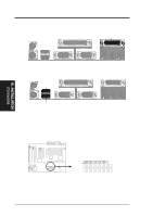
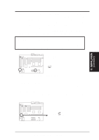
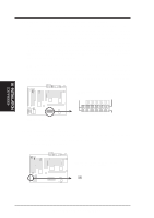
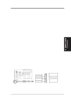
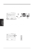
III. INSTALLATION (Connectors) III. INSTALLATION 13. Power LED Lead (PANEL) The system power LED lights when the system's power is on. 14. SMI Suspend Switch Lead (PANEL) This allows the user to manually place the system into a suspend mode or "Green" mode where system activity will be instantly decreased to save electricity and expand the life of certain components when the system is not in use. This 2-pin connector (see the figure below) connects to the case-mounted suspend switch. If you do not have a switch for the connector, you may use the "Turbo Switch" since it does not have a function. SMI is activated when it detects a short to open moment and therefore leaving it shorted will not cause any problems. May require one or two pushes depending on the position of the switch. Wake-up can be controlled by settings in the BIOS but the keyboard will always allow wakeup (the SMI lead cannot wake-up the system). If you want to use this connector, "Suspend Switch" in the Power Management Setup of the BIOS SOFTWARE section should be on the default setting of Enable. 15. ATX Power Switch (PANEL) The system power is controlled by a momentary switch connected to this lead. Pushing the button once will switch the system ON. The system power LED lights when the system's power is on. 16. Reset Switch Lead (PANEL) This 2-pin connector connects to the case-mounted reset switch for rebooting your computer without having to turn off your power switch This is a preferred method of rebooting in order to prolong the life of the system's power supply. 17. Keyboard Lock Switch Lead & System Power LED (PANEL) This 5-pin connector connects to the case-mounted keyboard lock switch for locking the keyboard and also to connect the system power LED. The system power LED lights when the system's power is on (same as Power LED). 18. Speaker Connector (PANEL) This 4-pin connector connects to the case-mounted speaker. R System Panel Connections Power LED +5V GND SMI Lead GND ATX Power Switch GND Reset SW GND +5V System NC GND Power LED LOCK Keyboard Lock GND +5V GND Speaker GND Connector SPKR ASUS KN97-X User's Manual 33
-
 1
1 -
2
-
3
-
4
-
5
-
6
-
7
-
8
-
9
-
10
-
11
-
12
-
13
-
14
-
15
-
16
-
17
-
18
-
19
-
20
-
21
-
22
-
23
-
24
-
25
-
26
-
27
-
 28
28 -
 29
29 -
 30
30 -
 31
31 -
 32
32 -
 33
33 -
 34
34 -
 35
35 -
 36
36 -
 37
37 -
 38
38 -
39
-
40
-
41
-
42
-
43
-
44
-
45
-
46
-
47
-
48
-
49
-
50
-
51
-
52
-
53
-
54
-
55
-
56
-
57
-
58
-
59
-
60
-
61
-
62
-
63
-
64
 |
 |
