Asus KN97 User Manual - Page 63
Setting the INT Assignment, Terminator Settings
 |
View all Asus KN97 manuals
Add to My Manuals
Save this manual to your list of manuals |
Page 63 highlights
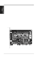
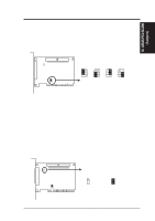
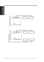
VI. ASUS PCI-SC200 (Jumpers) VI. ASUS PCI-SC200 SCSI Card Setting the INT Assignment You must use PCI INT A setting in order to properly assign the card's interrupt. On the ASUS PCI-SC200, you assign the INT by setting jumper JP1 or JP2. The default setting for the card already is INT A, so you do not need to change the setting to use the ASUS PCI-SC200 with this motherboard. JP JP 12 1 2 3 JP JP 12 1 2 3 INT A (Def) INT B JP JP 12 1 2 3 INT C Interrupt Settings (A, B, C, or D) JP JP 12 1 2 3 INT D Terminator Settings SCSI devices are connected together in a "chain" by cables. Internal devices connect to the ASUS PCI-SC200 with a fifty-pin flat ribbon cable. External devices connect to the external port with a SCSI-2 cable. If there are more than one internal or external devices, additional devices are connected with cables to form a "daisy chain." The SCSI chain must be "terminated" at both ends, or the devices in the chain will not work properly. Many SCSI devices use a set of terminating resistors to terminate the device. The ASUS PCI-SC200 has "active" termination that you set using jumper JP5. If you need to terminate the ASUS PCI-SC200, you do it by setting the jumper. The are two settings, "terminated" and "not terminated," as shown below. JP JP 5 5 Terminated (Default) Not Terminated Terminator Setting (Terminated / Not Terminated) ASUS KN97-X User's Manual 63
-
 1
1 -
2
-
3
-
4
-
5
-
6
-
7
-
8
-
9
-
10
-
11
-
12
-
13
-
14
-
15
-
16
-
17
-
18
-
19
-
20
-
21
-
22
-
23
-
24
-
25
-
26
-
27
-
28
-
29
-
30
-
31
-
32
-
33
-
34
-
35
-
36
-
37
-
38
-
39
-
40
-
41
-
42
-
43
-
44
-
45
-
46
-
47
-
48
-
49
-
50
-
51
-
52
-
53
-
54
-
55
-
56
-
57
-
 58
58 -
 59
59 -
 60
60 -
 61
61 -
 62
62 -
 63
63 -
 64
64
 |
 |
