Asus ME-99 ME-99 User Manual - Page 15
H/w Setup
 |
View all Asus ME-99 manuals
Add to My Manuals
Save this manual to your list of manuals |
Page 15 highlights
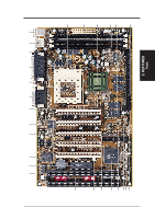
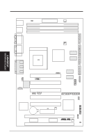
3. H/W SETUP Layout Contents 3. HARDWARE SETUP 3.2 Layout Contents Motherboard Settings 1) KB WAKEUP 2) DSW1-6, DSW1-7 3) DSW1-8 4) DSW2-5 5) DSW2-6 6) DSW2-7 7) DSW2-8 8) DSW1-1, 2, 3, 4 9) DSW1-5 10) DSW2-1, 2, 3, 4 p.18 Keyboard Wake Up Setting (Enable/Disable) p.19 I/O Voltage Setting (+0.1V/Normal) p.19 CPU Core Voltage (Vcore) Setting (+0.1V/Normal) p.20 Onboard VGA Setting (Enable/Disable) p.20 VGA Frame Buffer Setting (UMA/Non-UMA) p.21 LCD Setting (Enable/Disable) p.21 Onboard Audio Setting (Enable/Disable) p.22 CPU External Frequency Setting p.22 Memory Transfer Mode Setting (SYNC/ASYNC) p.23 CPU Core:External Frequency Multiple Setting Expansion Slots 1) DIMM1, DIMM2, DIMM3 p.24 168-Pin DIMM Memory Support 2) Socket 370 p.26 Central Processing Unit (CPU) Socket 3) SLOT1, SLOT2 p.27 16-bit ISA Bus Expansion Slots* 4) PCI1, PCI2, PCI3, PCI4, PCI5 p.27 32-bit PCI Bus Expansion Slots Connectors 1) PS2KBMS p.29 PS/2 Mouse Connector (6-pin female) 2) PS2KBMS p.29 PS/2 Keyboard Connector (6-pin female) 3) USB p.30 Universal Serial BUS Ports 1 & 2 (Two 4-pin female) 4) PRINTER p.30 Parallel Port Connector (25-pin female) 5) COM1 p.30 Serial Port COM1 Connector (9-pin male) 6) VGA p.31 Monitor (VGA) Output Connector (15-pin female) 7) GAME_AUDIO p.31 Joystick/Midi Connector (15-pin female) (optional) 8) GAME_AUDIO p.31 Audio Port Connectors (Three 1/8" female) (optional) 9) PRIMARY/SECONDARYIDE p.32 Primary/Secondary IDE Connectors (Two 40-1pins) 10) FLOPPY p.32 Floppy Disk Drive Connector (34-1pins) 11) WOL_CON p.33 Wake-On-LAN Connector (3 pins) 12) WOR p.33 Wake-On-Ring Connector (2 pins) 13) IDE p.34 IDE Activity LED (2 pins) 14) CHA_, CPU_, PWR_FAN p.34 Chassis, CPU, Power Supply Fan Connectors (Three 3-pin) 15) AUX, MODEM, CD2, CD1 p.35 Internal Audio Connectors (Four 4-pin) 16) IR p.35 IrDA-Compliant Infrared Module Connector (5 pins) 17) SCART p.36 TV Out Header (12-1 pins) 18) LCDHD p.36 LCD Header (20 pins) 19) SMB p.37 SMBus Connector (5-1 pins) 20) COM2 p.37 Serial Port COM2 Header (10-1 pins) (Cont'd on next page) *The integrated hardware monitor uses the address 290H-297H so legacy ISA cards must not use this address; otherwise, conflicts will occur. ASUS ME-99 User's Manual 15
-
 1
1 -
2
-
3
-
4
-
5
-
6
-
7
-
8
-
9
-
 10
10 -
 11
11 -
 12
12 -
 13
13 -
 14
14 -
 15
15 -
 16
16 -
 17
17 -
 18
18 -
 19
19 -
 20
20 -
21
-
22
-
23
-
24
-
25
-
26
-
27
-
28
-
29
-
30
-
31
-
32
-
33
-
34
-
35
-
36
-
37
-
38
-
39
-
40
-
41
-
42
-
43
-
44
-
45
-
46
-
47
-
48
-
49
-
50
-
51
-
52
-
53
-
54
-
55
-
56
-
57
-
58
-
59
-
60
-
61
-
62
-
63
-
64
-
65
-
66
-
67
-
68
-
69
-
70
-
71
-
72
-
73
-
74
-
75
-
76
-
77
-
78
-
79
-
80
-
81
-
82
-
83
-
84
-
85
-
86
-
87
-
88
-
89
-
90
-
91
-
92
-
93
-
94
-
95
-
96
-
97
-
98
-
99
-
100
-
101
-
102
-
103
-
104
 |
 |
