Asus ME-99 ME-99 User Manual - Page 36
Motherboard Settings
 |
View all Asus ME-99 manuals
Add to My Manuals
Save this manual to your list of manuals |
Page 36 highlights
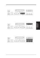
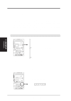
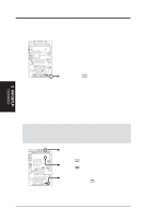
3. HARDWARE SETUP 17) TV Out Connector (12-1 pin SCART) This optional connector allows you to connect your computer directly to a TV with a SCART socket. NOTE: This connector is available only on motherboards with optional SCART interface support. 01 01 01 ME-99 ® ME-99 LCD Header LCDHD 20 10 11 1 20: (No connection) 19: (No connection) 18: TX2+ 17: GND 16: TX115: TX0+ 14: GND 13: TXC12: 0+5V 11: FDDCDAT 10: (No connection) 9: GND 8: TX27: TX1+ 6: GND 5: TX04: TXC+ 3: GND 2: PLSENSE 1: FDDCCLK 18) LCD Header (20-pin LCDHD) This header supports the provided LCD cable with mounting bracket. Connect the cable to this header and mount the bracket to the case on a free expansion slot. You can make available the LCD port by setting the DSW2-7 switch to ON (see 3.4 Motherboard Settings). NOTE: This connector is available only on motherboards with optional Digital Flat Panel (DFP) interface support. 01 01 01 ME-99 ® ME-99 LCD Header LCDHD 20 10 11 1 20: (No connection) 19: (No connection) 18: TX2+ 17: GND 16: TX115: TX0+ 14: GND 13: TXC12: 0+5V 11: FDDCDAT 10: (No connection) 9: GND 8: TX27: TX1+ 6: GND 5: TX04: TXC+ 3: GND 2: PLSENSE 1: FDDCCLK 3. H/W SETUP Connectors 36 ASUS ME-99 User's Manual
-
 1
1 -
2
-
3
-
4
-
5
-
6
-
7
-
8
-
9
-
10
-
11
-
12
-
13
-
14
-
15
-
16
-
17
-
18
-
19
-
20
-
21
-
22
-
23
-
24
-
25
-
26
-
27
-
28
-
29
-
30
-
 31
31 -
 32
32 -
 33
33 -
 34
34 -
 35
35 -
 36
36 -
 37
37 -
 38
38 -
 39
39 -
 40
40 -
 41
41 -
42
-
43
-
44
-
45
-
46
-
47
-
48
-
49
-
50
-
51
-
52
-
53
-
54
-
55
-
56
-
57
-
58
-
59
-
60
-
61
-
62
-
63
-
64
-
65
-
66
-
67
-
68
-
69
-
70
-
71
-
72
-
73
-
74
-
75
-
76
-
77
-
78
-
79
-
80
-
81
-
82
-
83
-
84
-
85
-
86
-
87
-
88
-
89
-
90
-
91
-
92
-
93
-
94
-
95
-
96
-
97
-
98
-
99
-
100
-
101
-
102
-
103
-
104
 |
 |
