Asus ME-99 ME-99 User Manual - Page 39
ASUS ME-99 User's Manual, System Management Interrupt Switch Lead 2-pin SMI, System Message LED Lead
 |
View all Asus ME-99 manuals
Add to My Manuals
Save this manual to your list of manuals |
Page 39 highlights
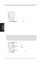
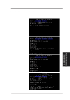
3. HARDWARE SETUP 26) System Management Interrupt Switch Lead (2-pin SMI) This allows the user to manually place the system into a suspend mode or "Green" mode, where system activity is decreased to save electricity and expand the life of certain components when the system is not in use. This 2-pin connector connects to the case-mounted suspend switch. If you do not have a switch for the connector, you may use the "Turbo Switch." SMI is activated when it detects a short to open moment and therefore leaving it shorted will not cause any problems. This may require one or two presses depending on the position of the switch. Wake-up can be controlled by settings in the BIOS but the keyboard will always allow wake-up (the SMI lead cannot wake up the system). 27) System Message LED Lead (2-pin LED) This indicates whether a message has been received from a fax/modem. The LED will remain lit when there is no signal and blink when there is data transfer or waiting in the inbox. This function requires ACPI OS and driver support. 28) ATX Power Supply Connector (20-pin block ATXPWR) This connector connects to an ATX power supply. The plug from the power supply will only insert in one orientation because of the different hole sizes. Find the proper orientation and push down firmly making sure that the pins are aligned. IMPORTANT: Make sure that your ATX power supply can supply at least 10mA on the +5-volt standby lead (+5VSB). You may experience difficulty in powering ON your system if your power supply cannot support the load. For WakeOn-LAN support, your ATX power supply must supply at least 720mA +5VSB. 3. H/W SETUP Connectors +5.0 Volts +5.0 Volts -5.0 Volts Ground Ground Ground Power Supply On Ground -12.0 Volts +3.3 Volts 01 01 01 +12.0 Volts +5V Standby Power Good Ground +5.0 Volts Ground +5.0 Volts Ground +3.3 Volts +3.3 Volts ME-99 ® ME-99 ATX Power Connector ASUS ME-99 User's Manual 39
-
 1
1 -
2
-
3
-
4
-
5
-
6
-
7
-
8
-
9
-
10
-
11
-
12
-
13
-
14
-
15
-
16
-
17
-
18
-
19
-
20
-
21
-
22
-
23
-
24
-
25
-
26
-
27
-
28
-
29
-
30
-
31
-
32
-
33
-
 34
34 -
 35
35 -
 36
36 -
 37
37 -
 38
38 -
 39
39 -
 40
40 -
 41
41 -
 42
42 -
 43
43 -
 44
44 -
45
-
46
-
47
-
48
-
49
-
50
-
51
-
52
-
53
-
54
-
55
-
56
-
57
-
58
-
59
-
60
-
61
-
62
-
63
-
64
-
65
-
66
-
67
-
68
-
69
-
70
-
71
-
72
-
73
-
74
-
75
-
76
-
77
-
78
-
79
-
80
-
81
-
82
-
83
-
84
-
85
-
86
-
87
-
88
-
89
-
90
-
91
-
92
-
93
-
94
-
95
-
96
-
97
-
98
-
99
-
100
-
101
-
102
-
103
-
104
 |
 |
