Asus P2L-VM P2L-VM User Manual - Page 12
Iii. Installation
 |
View all Asus P2L-VM manuals
Add to My Manuals
Save this manual to your list of manuals |
Page 12 highlights
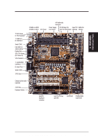
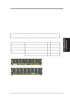
PARALLEL PORT FS0 FS1 FS2 01 23 45 III. INSTALLATION Motherboard Layout III. INSTALLATION ASUS P2L-VM/P2E-VM Motherboard Layout 2 MB SDRAM PS/2 Top: Mouse Bottom: Keyboard USB Top: USB 1 Bottom: USB 2 COM1 KBPWR ATXPWR PWR_FAN Power Supply Fan Control TV_CON (optional) ImpacTV2 ATX Power Connector ATI Multimedia Connector (optional) Chipset Row INT_EN (optional) DIMM Socket 1 (64/72-bit, 168-pin module) 2 MB SDRAM DIMM Socket 2 (64/72-bit, 168-pin module) DIMM Socket 3 (64/72-bit, 168-pin module) P2L-VM only BUS Frequency CPU_FAN Intel 440LX RTCPU or 440EX AGPset VGAEN ATI 3D Rage Pro AGP 2X VGA Chipset 2 MB SDRAM 2 MB SDRAM GAME/AUDIO (optional) VGA Single Edge Contact Slot Out Line In Line COM2 Multi-I/O, Keyboard Controller WOL_CON In Mic CD1 CD2 (optional) SPDIF AUX 16-bit Audio Chipset Hardware Monitor PCI Slot 1 PCI Slot 2 R PCI Slot 3 ISA Slot 1 ISA Slot 2 Intel PIIX4 PCIset, RTC CR2032 3V Lithium Cell BIOS Power CHA_FAN SMB CLRCMOS Freq. Ratio IR BF0 BF1 BF2 BF3 IDELED ASUS ASIC VPANEL Panel Connectors 2Mbit Flash EEPROM (Programmable BIOS) Floppy Drives Secondary IDE Primary IDE (Greyed items are optional at the time of purchase.) 12 ASUS P2L-VM/P2E-VM User's Manual
-
 1
1 -
2
-
3
-
4
-
5
-
6
-
 7
7 -
 8
8 -
 9
9 -
 10
10 -
 11
11 -
 12
12 -
 13
13 -
 14
14 -
 15
15 -
 16
16 -
 17
17 -
18
-
19
-
20
-
21
-
22
-
23
-
24
-
25
-
26
-
27
-
28
-
29
-
30
-
31
-
32
-
33
-
34
-
35
-
36
-
37
-
38
-
39
-
40
-
41
-
42
-
43
-
44
-
45
-
46
-
47
-
48
-
49
-
50
-
51
-
52
-
53
-
54
-
55
-
56
-
57
-
58
-
59
-
60
-
61
-
62
-
63
-
64
-
65
-
66
-
67
-
68
-
69
-
70
-
71
-
72
-
73
-
74
-
75
-
76
-
77
-
78
-
79
-
80
-
81
-
82
-
83
-
84
-
85
-
86
-
87
-
88
-
89
-
90
-
91
-
92
-
93
-
94
-
95
-
96
-
97
-
98
-
99
-
100
-
101
-
102
-
103
-
104
-
105
-
106
-
107
-
108
-
109
-
110
-
111
-
112
-
113
-
114
-
115
-
116
 |
 |
