Asus P2L-VM P2L-VM User Manual - Page 15
Riii. Installation
 |
View all Asus P2L-VM manuals
Add to My Manuals
Save this manual to your list of manuals |
Page 15 highlights
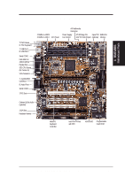
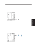
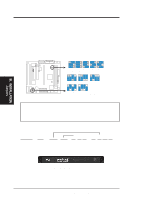
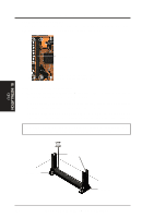
III. INSTALLATION 3. Real Time Clock (RTC) RAM (CLRCMOS) The CMOS RAM is powered by the onboard button cell battery. To clear the RTC data: (1) Unplug your computer, (2) Short solder points, (3) Turn on your computer, (4) Hold down during bootup and enter BIOS setup to reenter user preferences. RTC RAM CLRCMOS Clear CMOS [short solder points momentarily] R III. INSTALLATION Jumpers P2L-VM/P2E-VM Clear RTC RAM CLRCMOS 4. Keyboard Power Up (KBPWR) This allows you to disable or enable the keyboard power up function. Set this jumper to Enable if you wish to use your keyboard (by pressing the spacebar) to power up your computer. This feature requires an ATX power supply that can supply at least 300mAmp on the +5VSB lead. The default is set to Disable because not all computers have the appropriate ATX power supply. Your computer will not power on if you set this to Enable and if you do not have the right ATX power supply. Setting KBPWR Disable [1-2] (default) Enable [2-3] KBPWR 1 2 3 Disable (Default) KBPWR 1 2 3 Enable R P2L-VM/P2E-VM Keyboard Power Up ASUS P2L-VM/P2E-VM User's Manual 15
-
 1
1 -
2
-
3
-
4
-
5
-
6
-
7
-
8
-
9
-
 10
10 -
 11
11 -
 12
12 -
 13
13 -
 14
14 -
 15
15 -
 16
16 -
 17
17 -
 18
18 -
 19
19 -
 20
20 -
21
-
22
-
23
-
24
-
25
-
26
-
27
-
28
-
29
-
30
-
31
-
32
-
33
-
34
-
35
-
36
-
37
-
38
-
39
-
40
-
41
-
42
-
43
-
44
-
45
-
46
-
47
-
48
-
49
-
50
-
51
-
52
-
53
-
54
-
55
-
56
-
57
-
58
-
59
-
60
-
61
-
62
-
63
-
64
-
65
-
66
-
67
-
68
-
69
-
70
-
71
-
72
-
73
-
74
-
75
-
76
-
77
-
78
-
79
-
80
-
81
-
82
-
83
-
84
-
85
-
86
-
87
-
88
-
89
-
90
-
91
-
92
-
93
-
94
-
95
-
96
-
97
-
98
-
99
-
100
-
101
-
102
-
103
-
104
-
105
-
106
-
107
-
108
-
109
-
110
-
111
-
112
-
113
-
114
-
115
-
116
 |
 |
