Asus P4S8X P4S8X User Manual - Page 43
ASUS P4S8X motherboard user guide, IDE Connectors 40-1 pin PRI_IDE, SEC_IDE, PRI_ATA133 - motherboard specifications
 |
View all Asus P4S8X manuals
Add to My Manuals
Save this manual to your list of manuals |
Page 43 highlights
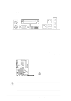
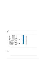
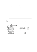
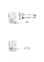
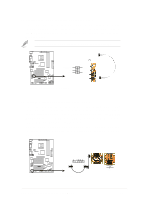
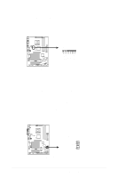
10. IDE Connectors (40-1 pin PRI_IDE / SEC_IDE, PRI_ATA133) Three connectorS support the UltraDMA133/100/66 IDE hard disk ribbon cable provided with the motherboard. Connect the cable's blue connector to the PRI_IDE (recommended) or to the SEC_IDE connector; then connect the gray connector to the UltraDMA133/100/66 slave device (hard disk drive) and the black connector to the UltraDMA133/100/66 master device. It is recommended that non-UltraDMA133/100/66 devices be connected to the secondary IDE connector. If installing two hard disks, configure the second drive as a slave device; set the slave hard disk jumper according to the HDD instructions. ~ The PRI_ATA133 connector supports only one hard disk drive for use in a RAID array. The PRI_ATA133 connector supports either RAID1/0 in combination with either of the Serial ATA connectors. (See pages 37 and 82 for more information about RAID.) ~ BIOS supports specific device bootup. If more than two UltraDMA133/100/66 devices are used, purchase another UltraDMA133/ 100/66 cable. It is possible to configure two hard disks as master devices by using two separate ribbon cables, one for the primary IDE connector, and another for the secondary IDE connector. Pin 20 on each IDE connector is removed to match the covered hole on the UltraDMA cable connector. This prevents incorrect orientation when you connect the cables. PIN 1 NOTE: Orient the red markings (usually zigzag) on the IDE ribbon cable to PIN 1. P4S8X ® PIN 1 P4S8X IDE Connectors 1. For UltraDMA133/100/66 IDE devices, use an 80-conductor IDE cable. The UltraDMA/66 cable included in the motherboard package also supports UltraDMA133. 2. Always connect ribbon cables with the red stripe to Pin 1 on the connectors. Pin 1 is usually on the side closest to the power connector on hard drives and CD-ROM drives, but may be on the opposite side on floppy disk drives. SEC_IDE PRI_IDE PRI_ATA133 ASUS P4S8X motherboard user guide 31
-
 1
1 -
2
-
3
-
4
-
5
-
6
-
7
-
8
-
9
-
10
-
11
-
12
-
13
-
14
-
15
-
16
-
17
-
18
-
19
-
20
-
21
-
22
-
23
-
24
-
25
-
26
-
27
-
28
-
29
-
30
-
31
-
32
-
33
-
34
-
35
-
36
-
37
-
 38
38 -
 39
39 -
 40
40 -
 41
41 -
 42
42 -
 43
43 -
 44
44 -
 45
45 -
 46
46 -
 47
47 -
 48
48 -
49
-
50
-
51
-
52
-
53
-
54
-
55
-
56
-
57
-
58
-
59
-
60
-
61
-
62
-
63
-
64
-
65
-
66
-
67
-
68
-
69
-
70
-
71
-
72
-
73
-
74
-
75
-
76
-
77
-
78
-
79
-
80
-
81
-
82
-
83
-
84
-
85
-
86
-
87
-
88
-
89
-
90
-
91
-
92
-
93
-
94
-
95
-
96
-
97
-
98
-
99
-
100
-
101
-
102
-
103
-
104
-
105
-
106
-
107
-
108
-
109
-
110
-
111
-
112
-
113
-
114
-
115
-
116
-
117
-
118
-
119
-
120
-
121
-
122
-
123
-
124
-
125
-
126
-
127
-
128
-
129
-
130
-
131
-
132
-
133
-
134
-
135
-
136
-
137
-
138
-
139
-
140
-
141
-
142
-
143
-
144
 |
 |
