Asus SK8N SK8N User Manual
Asus SK8N Manual
 |
View all Asus SK8N manuals
Add to My Manuals
Save this manual to your list of manuals |
Asus SK8N manual content summary:
- Asus SK8N | SK8N User Manual - Page 1
Motherboard SK8N User Guide - Asus SK8N | SK8N User Manual - Page 2
, without the express written permission of ASUSTeK COMPUTER INC. ("ASUS"). Product warranty or service will not be extended if: (1) the AS A COMMITMENT BY ASUS. ASUS ASSUMES NO RESPONSIBILITY OR LIABILITY FOR ANY ERRORS OR INACCURACIES THAT MAY APPEAR IN THIS MANUAL, INCLUDING THE PRODUCTS AND - Asus SK8N | SK8N User Manual - Page 3
vii About this guide viii How this guide is organized viii Conventions used in this guide ix Typography ix ASUS features 1-4 Chapter 2: Hardware information 2.1 Before you proceed 2-1 2.2 Motherboard overview 2-2 2.2.1 Placement direction 2-2 2.2.2 Screw holes 2-2 2.2.3 Motherboard - Asus SK8N | SK8N User Manual - Page 4
up 3.1 Starting up for the first time 3-1 3.2 Powering off the computer 3-2 3.2.1 Using the OS shut down function 3-2 3.2.2 Using the from PC 4-3 4.1.4 Using ASUS EZ Flash to update the BIOS 4-4 4.1.5 Recovering the BIOS with CrashFree BIOS 2 ....... 4-5 4.1.6 ASUS Update 4-7 4.2 BIOS Setup - Asus SK8N | SK8N User Manual - Page 5
4-34 4.7 Exit menu 4-36 Chapter 5: Software support 5.1 Install an operating system 5-1 5.2 Support CD information 5-1 5.2.1 Running the support CD 5-1 5.2.2 Drivers menu 5-2 5.2.3 Utilities menu 5-3 5.2.4 ASUS Contact Information 5-4 5.2.5 Other information 5-5 5.3 Software Information - Asus SK8N | SK8N User Manual - Page 6
. This equipment generates, uses and can radiate radio frequency energy and, if not installed and used in accordance with manufacturer's instructions, may cause harmful interference to radio communications. However, there is no guarantee that interference will not occur in a particular installation - Asus SK8N | SK8N User Manual - Page 7
Contact a qualified service technician or your retailer. Operation safety • Before installing the motherboard and adding devices on it, carefully read all the manuals that came with . • If you encounter technical problems with the product, contact a qualified service technician or your retailer. vii - Asus SK8N | SK8N User Manual - Page 8
information you need when installing the motherboard. How this guide is organized This manual contains the following parts: • Chapter 1: Product introduction This chapter describes the motherboard features of the and the new technologies it supports. • Chapter 2: Hardware information This chapter - Asus SK8N | SK8N User Manual - Page 9
used in this guide To make sure that you perform certain tasks properly, take note of the following symbols used throughout this manual. DANGER/WARNING: ASUS websites The ASUS websites worldwide provide updated information on ASUS hardware and software products. Refer to the ASUS contact - Asus SK8N | SK8N User Manual - Page 10
and RAID 0+1 configurations ALC 650 6-channel audio controller support for S/PDIF out interface CK8 MAC + Realtek RTL8201BL PHY up to 300 MHz at 1 MHz increments ASUS JumperFree Adjustable CPU Frequency Multiple ASUS MyLogo2 ASUS EZ Flash ASUS CrashFree BIOS2 ASUS Q-Fan 1 x Parallel port 1 x Serial - Asus SK8N | SK8N User Manual - Page 11
features Industry standard Manageability Power Requirement Form Factor Support CD contents Floppy disk drive connector Primary/Secondary 12 in x 9.6 in (30.5 cm x 24.4 cm) Device drivers ASUS PC Probe Trend Micro™ PC-cillin 2002 anti-virus software * Specifications are subject to change without notice - Asus SK8N | SK8N User Manual - Page 12
xii - Asus SK8N | SK8N User Manual - Page 13
Chapter 1 This chapter describes the motherboard features and the new technologies it supports. Product introduction - Asus SK8N | SK8N User Manual - Page 14
Chapter summary 1.1 Welcome 1-1 1.2 Package contents 1-1 1.3 Special features 1-2 ASUS SK8N motherboard - Asus SK8N | SK8N User Manual - Page 15
in the world of power computing! Before you start installing the motherboard, and hardware devices on it, check the items in your package with the list below. 1.2 Package contents Check your motherboard package for the following items. ASUS SK8N motherboard ASUS support CD 2 x SATA cable 1 x 4 port - Asus SK8N | SK8N User Manual - Page 16
designed to increase the communication speed between integrated circuits in computers, networking and telecommunicatons equipment up to 48 times faster than other existing technologies. Serial ATA solution The motherboard supports two interfaces compliant to the Serial ATA (SATA) specification, an - Asus SK8N | SK8N User Manual - Page 17
S/PDIF out The motherboard supports S/PDIF out function that turns your computer into a high-end entertainment system with digital connectivity to powerful speaker systems. IEEE 1394 support The IEEE 1394 interface provides high-speed and flexible PC connectivity to a wide range of peripherals and - Asus SK8N | SK8N User Manual - Page 18
to restore the original BIOS data from the ASUS support CD in case when the BIOS codes and data are corrupted. This protection eliminates the need to buy a replacement ROM chip. See page 4-5. ASUS MyLogo2™ This new feature present in the SK8N motherboard allows you to personalize and add style to - Asus SK8N | SK8N User Manual - Page 19
Chapter 2 This chapter lists the hardware setup procedures that you have to perform when installing system components. It includes description of the jumpers and connectors on the motherboard. Hardware information - Asus SK8N | SK8N User Manual - Page 20
Chapter summary 2.1 Before you proceed 2-1 2.2 Motherboard overview 2-2 2.3 Central Processing Unit (CPU 2-6 2.4 System memory 2-11 2.5 Expansion slots 2-15 2.6 Jumpers 2-18 2.7 Connectors 2-20 ASUS SK8N motherboard - Asus SK8N | SK8N User Manual - Page 21
before you install motherboard components or change any motherboard settings. 1. severe damage to the motherboard, peripherals, and/or components. Onboard LED The motherboard comes with a standby before removing or plugging in any motherboard component. The illustration below shows the location - Asus SK8N | SK8N User Manual - Page 22
it. Make sure to unplug the power cord before installing or removing the motherboard. Failure to do so may cause you physical injury and damage motherboard components. 2.2.1 Placement direction When installing the motherboard, make sure that you place it into the chassis in the correct orientation - Asus SK8N | SK8N User Manual - Page 23
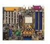
30.5cm (12.0in) 2.2.3 Motherboard layout 24.5cm (9.6in) PS/2KBMS T: Mouse B: Keyboard COM1 DDR DIMM_B2 (64 bit,184-pin module) SATA_RAID2 PRI_RAID1 CLRTC1 CHA_FAN1 PANEL1 ® PROMISE PDC20378 RAID Controller SATA_RAID1 SB_PWR1 USB56 FLOPPY1 SEC_IDE PRI_IDE ASUS SK8N motherboard 2-3 - Asus SK8N | SK8N User Manual - Page 24
2.2.4 Layout Contents Expansion slots 1. PCI slots 2. AGP slot 3. DDR DIMM slots p. 2-17 p. 2-17 p. 2-11 Jumpers 1. Clear RTC RAM (3-pin CLRTC1) 2. Boot Block Write-protect (2-pin J1) 3. USB device wake-up (3-pin USBPWR12, USBPWR34) p. 2-18 p. 2-19 p. 2-19 Rear Panel Connectors 1. PS/2 mouse - Asus SK8N | SK8N User Manual - Page 25
) - Hard Disk Activity LED (Red 2-pin IDE_LED) p. 2-21 p. 2-21 p. 2-22 p. 2-22 p. 2-23 p. 2-24 p. 2-24 p. 2-24 p. 2-24 p. 2-25 p. 2-25 p. 2-26 p. 2-27 p. 2-27 p. 2-27 p. 2-28 p. 2-28 p. 2-29 ASUS SK8N motherboard 2-5 - Asus SK8N | SK8N User Manual - Page 26
2.3 Central Processing Unit (CPU) 2.3.1 Overview The motherboard comes with a surface mount 940-pin Zero Insertion Force (ZIF) socket designed for the AMD Athlon™ the CPU Follow these steps to install a CPU. 1. Locate the 940-pin ZIF socket on the motherboard. 2-6 Chapter 2: Hardware information - Asus SK8N | SK8N User Manual - Page 27
is in place, push down the socket lever to secure the CPU. The lever clicks on the side tab to indicate that it is locked. ASUS SK8N motherboard 2-7 - Asus SK8N | SK8N User Manual - Page 28
module base when installing the CPU or installing other motherboard components. CPU Fan CPU Heatsink Retention Module Base Retention bracket Retention bracket lock Your boxed CPU heatsink and fan assembly should come with installation instructions for the CPU, heatsink, and the retention mechanism - Asus SK8N | SK8N User Manual - Page 29
place. Make sure that the fan and heatsink assembly perfectly fits the retention mechanism module base, otherwise you cannot snap the retention bracket in place. ASUS SK8N motherboard 2-9 - Asus SK8N | SK8N User Manual - Page 30
the CPU fan cable When the fan, heatsink, and the retention mechanism are in place, connect the CPU fan cable to the connector on the motherboard labeled CPU_FAN. CPU Fan Connector (CPU_FAN1) Don't forget to connect the CPU fan connector! Hardware monitoring errors may occur if you fail to plug - Asus SK8N | SK8N User Manual - Page 31
2.4 System memory 2.4.1 Overview The motherboard comes with four Double Data Rate (DDR) Dual Inline Memory Module (DIMM) sockets. The following figure illustrates than 4GB) due to the Southbridge resource allocation. 5. It is recommended to use the blue DIMM slots first. ASUS SK8N motherboard 2-11 - Asus SK8N | SK8N User Manual - Page 32
Qualified Vendor List The following table lists the PC2700 (DDR333) memory modules that have been tested and qualified for use with this motherboard. Size Vendor Model Brand 256MB Apacer 77.10632.112 Infineon 512MB Apacer 77.10732.112 Infineon 512MB Apacer 78.91052.111 Infineon 256MB - Asus SK8N | SK8N User Manual - Page 33
qualified for use with this motherboard. Size 256MB 512MB Vendor SAMSUNG support for 4 modules inserted into the blue & yellow slots as two pairs of Dual-channel memory configuration. Obtain DDR DIMMs only from ASUS qualified vendors for better system performance. Visit the ASUS website (www.asus - Asus SK8N | SK8N User Manual - Page 34
seated. Locked Retaining Clip 2.4.5 Removing a DIMM Follow these steps to remove a DIMM. 1. Simultaneously press the retaining clips outward to unlock the DIMM. Support the DIMM lightly with your fingers when pressing the retaining clips. The DIMM might get damaged when it flips out with extra force - Asus SK8N | SK8N User Manual - Page 35
cards. The motherboard has five PCI slots and one Accelerated Graphics Port (AGP) slot. The following sub-sections describe the slots and the expansion cards that they support. Make sure the tables on the next page. 3. Install the software drivers for the expansion card. ASUS SK8N motherboard 2-15 - Asus SK8N | SK8N User Manual - Page 36
are usually available for ISA or PCI devices. IRQ assignments for this motherboard PCI slot 1 PCI slot 2 PCI slot 3 PCI slot 4 PCI INT D - - - When using PCI cards on shared slots, ensure that the drivers support "Share IRQ" or that the cards do not need IRQ assignments. Otherwise, conflicts will - Asus SK8N | SK8N User Manual - Page 37
cards are not supported in this motherboard. SK8N ® Keyed for 1.5v SK8N Accelerated Graphics Port (AGP) If installing the ATi 9500 or 9700 Pro Series VGA cards, use only the card version PN xxx-xxxxx-30 or later, for optimum performance and overclocking stability. ASUS SK8N motherboard 2-17 - Asus SK8N | SK8N User Manual - Page 38
onboard button cell battery. To erase the RTC RAM: 1. Turn OFF the computer and unplug the power cord. 2. Remove the onboard battery. 3. Move the pins 1-2. 4. Replace the battery. 5. Plug the power cord and turn ON the computer. 6. Hold down the key during the boot process and enter BIOS setup - Asus SK8N | SK8N User Manual - Page 39
Write Protect 3. USB device wake-up (3-pin USBPWR1234) Set these jumpers to +5V to wake up the computer from S1 sleep mode (CPU stopped, DRAM refreshed, system running in low power mode) using the connected USB (+5VSB) whether under normal condition or in sleep mode. ASUS SK8N motherboard 2-19 - Asus SK8N | SK8N User Manual - Page 40
2.7 Connectors 2.7.1 Rear panel connectors 1 2 3 4 5 6 7 11 10 9 8 1. PS/2 mouse port. This green 6-pin connector is for a PS/2 mouse. 2. Parallel port. This 25-pin port connects a parallel printer, a scanner, or other devices. 3. IEEE 1394 port. This 6-pin IEEE 1394 port provides high- - Asus SK8N | SK8N User Manual - Page 41
PS/2 keyboard. 2.7.2 Internal connectors 1. IDE connectors (40-1 pin PRI_IDE, SEC_IDE) This connector supports the provided UltraATA100 IDE hard disk ribbon cable. Connect the cable's blue connector to the primary (usually zigzag) on the IDE ribbon cable to PIN 1. PIN 1 ASUS SK8N motherboard 2-21 - Asus SK8N | SK8N User Manual - Page 42
2. Floppy disk drive connector (34-1 pin FLOPPY1) This connector supports the provided floppy drive ribbon cable. After connecting one end to the motherboard, connect the other end to the floppy drive. (Pin 5 is removed to prevent incorrect insertion when using ribbon cables with pin 5 plug). SK8N - Asus SK8N | SK8N User Manual - Page 43
the Serial ATA cable eliminates the problem caused by the wide, flat ribbon cables of the Parallel ATA interface. • Hot plug support for Serial ATA drive and connections are not available in this motherboard. • Install Windows® XP™ Service Pack 1 when using Serial ATA. ASUS SK8N motherboard 2-23 - Asus SK8N | SK8N User Manual - Page 44
and Chassis Fan Connectors (3-pin CPU_FAN1, PWR_FAN1, CHA_FAN1) The fan connectors support cooling fans of 350mA~740mA (8.88W max.) or a total of 1A~2.22A (26.64W max.) at +12V. Connect the fan cables to the fan connectors on the motherboard, making sure that the black wire of each cable matches the - Asus SK8N | SK8N User Manual - Page 45
down firmly until the connectors completely fit. In addition to the 20-pin ATXPWR1 connector, this motherboard requires that you connect the 4-pin ATX +12V power plug to provide sufficient power to the CPU COM COM COM PS_ON# COM -12.0VDC +3.3VDC SK8N ATX Power Connector ASUS SK8N motherboard 2-25 - Asus SK8N | SK8N User Manual - Page 46
additional USB ports. The USB header complies with USB 2.0 specification that supports up to 480 Mbps connection speed. This speed advantage over the , and simultaneous running of high-speed peripherals. You must install the driver before you can use the USB 2.0 capability. SK8N USB+5V USB_P6USB_P6 - Asus SK8N | SK8N User Manual - Page 47
GND +12V TPB0GND TPA0- SK8N IEEE-1394 Connector NEVER connect a USB cable to any of the IEEE 1394 (orange) connectors. Doing so will damage the motherboard! ASUS SK8N motherboard 2-27 - Asus SK8N | SK8N User Manual - Page 48
11. Front panel audio connector (10-1 pin FP_AUDIO) This is an interface for the front panel audio cable that allow convenient connection and control of audio devices. By default, the pins labeled LINE_OUT_R/BLINE_OUT_R and the pins LINE_OUT_L/BLINE_OUT_L are shorted with jumper caps. Remove the - Asus SK8N | SK8N User Manual - Page 49
LED to light up. The System Panel connector is color-coded for easy and foolproof connection. Take note of the specific connector colors as described. ASUS SK8N motherboard 2-29 - Asus SK8N | SK8N User Manual - Page 50
2-30 Chapter 2: Hardware information - Asus SK8N | SK8N User Manual - Page 51
Chapter 3 This chapter describes the power up sequence, the vocal POST messages and ways of shutting down the system. Powering up - Asus SK8N | SK8N User Manual - Page 52
Chapter summary 3.1 Starting up for the first time 3-1 3.2 Powering off the computer 3-2 ASUS SK8N motherboard - Asus SK8N | SK8N User Manual - Page 53
test. Check the jumper settings and connections or call your retailer for assistance. 7. At power on, hold down to enter BIOS Setup. Follow the instructions in Chapter 4. ASUS SK8N motherboard 3-1 - Asus SK8N | SK8N User Manual - Page 54
, click the Start button, click Shut Down..., make sure that the Shut down option button is selected, then the OK button to shut down the computer. The power supply should turn off after Windows shuts down. If you are using Windows XP, click the Start button, click Turn Off - Asus SK8N | SK8N User Manual - Page 55
Chapter 4 This chapter tells how to change the system settings through the BIOS Setup menus. Detailed descriptions of the BIOS parameters are also provided. BIOS setup - Asus SK8N | SK8N User Manual - Page 56
Chapter summary 4.1 Managing and updating your BIOS 4-1 4.2 BIOS Setup program 4-9 4.3 Main Menu 4-12 4.4 Advanced Menu 4-15 4.5 Power Menu 4-27 4.6 Boot Menu 4-31 4.7 Exit Menu 4-36 ASUS SK8N motherboard - Asus SK8N | SK8N User Manual - Page 57
ASUS EZ Flash (Updates the BIOS using a floppy disk during POST.) 3. ASUS CrashFree BIOS2 (Updates the BIOS using a bootable floppy or the motherboard support CD.) 4. ASUS b. From your Windows desktop, click on Start, then select My Computer. c. Select the 3 1/2 Floppy Drive icon. d. Click File from - Asus SK8N | SK8N User Manual - Page 58
(www.asus.com) to download the latest BIOS file for your motherboard. Save the BIOS file to a bootable floppy disk. Write down the BIOS file name to a piece of paper. You need to type the exact BIOS file name at the prompt. 2. Copy the AFUDOS.EXE utility from the support CD to the - Asus SK8N | SK8N User Manual - Page 59
shown. Main filename Extension name A:\>afudos /oMYBIOS03.rom AMI Firmware Update Utility - Version 1.10 Copyright (C) 2002 American Megatrends, Inc. All rights reserved. Reading flash ..... 0x0008CC00 (9%) ASUS SK8N motherboard 4-3 - Asus SK8N | SK8N User Manual - Page 60
by simply pressing during the Power-On Self Tests (POST). To update the BIOS using ASUS EZ Flash: 1. Visit the ASUS website (www.asus.com) to download the latest BIOS file for your motherboard and rename the downloaded file as SK8N.ROM. Save the BIOS file to a floppy disk. 2. Reboot the - Asus SK8N | SK8N User Manual - Page 61
case the current BIOS on the motherboard fails or gets corrupted. 1. Prepare the support CD that came with the motherboard or a floppy disk that contains the motherboard BIOS before proceeding with the . Bad BIOS checksum. Starting BIOS recovery... Checking for floppy... ASUS SK8N motherboard 4-5 - Asus SK8N | SK8N User Manual - Page 62
is no floppy disk found in the drive, the system automatically checks the CD-ROM. 3. Place the support CD in the CD-ROM. The support CD contains the original BIOS for this motherboard. Bad BIOS checksum. Starting BIOS recovery... Checking for floppy... Floppy not found! Checking for CD-ROM... CD - Asus SK8N | SK8N User Manual - Page 63
utility is available in the support CD that comes with the motherboard package. ASUS Update requires an Internet connection either through a network or an Internet Service Provider (ISP). To install ASUS Update: 1. Insert the support CD into the CD-ROM drive. The Drivers menu appears. 2. Click the - Asus SK8N | SK8N User Manual - Page 64
updating/ downloading from the Internet, select the ASUS FTP site nearest you to avoid network traffic, or choose Auto Select. Click Next. 4. From the FTP site, select the BIOS version that you wish to download. Click Next. 5. Follow the instructions on the succeeding screens to complete the update - Asus SK8N | SK8N User Manual - Page 65
motherboard supports a programmable firmware that you can update using the provided utility described in section "4.1 Managing and updating your BIOS." Use the BIOS Setup program when you are installing a motherboard on the motherboard stores the Setup utility. When you start up the computer, the - Asus SK8N | SK8N User Manual - Page 66
:19] [Thu 03/27/2003] [1.44M, 3.5 in] Primary IDE Master Primary IDE Slave Secondary IDE Master Secondary IDE Slave System Information :[ST320413A] :[ASUS CD-S340] :[Not Detected] :[Not Detected] Use [ENTER], [TAB] or [SHIFT-TAB] to select a field. Use [+] or [-] to configure system time. Select - Asus SK8N | SK8N User Manual - Page 67
3.5 in] Primary IDE Master Primary IDE Slave Secondary IDE Master Secondary IDE Slave System Information :[ST320413A] :[ASUS CD-S340] :[Not Detected] :[Not Detected] The other items (Advanced, Power, Boot, and Exit) screen is a brief description of the selected item. ASUS SK8N motherboard 4-11 - Asus SK8N | SK8N User Manual - Page 68
:19] [Thu 03/27/2003] [1.44M, 3.5 in] Primary IDE Master Primary IDE Slave Secondary IDE Master Secondary IDE Slave System Information :[ST320413A] :[ASUS CD-S340] :[Not Detected] :[Not Detected] Use [ENTER], [TAB] or [SHIFT-TAB] to select a field. Use [+] or [-] to configure system time. Select - Asus SK8N | SK8N User Manual - Page 69
Supported Block Mode : 16 Sectors PIO Mode : Supported Ultra DMA : Ultra DMA-5 SMART Monitoring: Supported to Auto enables the LBA mode if the device supports this mode, and if the device was not previously sectors at a time if the device supports multi-sector transfer feature. When set to - Asus SK8N | SK8N User Manual - Page 70
PIO Mode [Auto] Selects the PIO mode. Configuration options: [Auto] [0] [1] [2] [3] [4] DMA Mode [Auto] Selects the DMA mode. Configuration options: [Auto] [SWDMA0] [SWDMA1] [SWDMA2] [MWDMA0] [MWDMA1] [MWDMA2] [UDMA0] [UDMA1] [UDMA2] [UDMA3] [UDMA4] [UDMA5] SMART Monitoring [Auto] Sets the Smart - Asus SK8N | SK8N User Manual - Page 71
value entered that is not in this range will have no effect or the system will be unstable if the selected FSB Speed is not supported. If the system fails due to overclocking, unplug the power cable; wait for 10 seconds then plug again to power source and restart system - Asus SK8N | SK8N User Manual - Page 72
CPU Voltage [ 1.55V] This item allows you to select a specific CPU Voltage. Take caution in setting CPU Voltage, a very high voltage may severely damage the CPU! Configuration options: [1.55V] [1.65V] [1.75V] 4.4.2 Chipset The Chipset menu items allow you to change the advanced chipset settings. - Asus SK8N | SK8N User Manual - Page 73
clock mode. Set by the code using [Auto] or select [Manual] to set using one of the standard values. Configuration options: [Auto] [Manual] Memclock Value [200 MHz] This item appears when Memclock Mode is access contention. Configuration options: [Auto] [Disabled] ASUS SK8N motherboard 4-17 - Asus SK8N | SK8N User Manual - Page 74
[Disable] Select Screen Select Item +- Change Option F1 General Help F10 Save and Exit ESC Exit Master ECC Enable [Disabled] This item enables or disables support on all nodes for ECC error detect and correction. Configuration options: [Disabled] [Enabled] 4-18 Chapter 4: BIOS Setup - Asus SK8N | SK8N User Manual - Page 75
.3 MAC interface. Configuration options: [Enabled] [Disabled] Onboard LAN Boot ROM [Disabled] This item enables or disables the onboard LAN Boot ROM. Configuration options: [Disabled] [Enabled] ASUS SK8N motherboard 4-19 - Asus SK8N | SK8N User Manual - Page 76
Controllers] Allows you to set the number of USB ports to activate. Configuration options: [Disabled] [Both Controllers] Legacy USB Support [Enabled] Allows you to enable or disable support for legacy USB devices. Setting to Auto allows the system to detect the presence of USB devices at startup. If - Asus SK8N | SK8N User Manual - Page 77
Emulation Type items appear only when there are installed USB devices. IOAPIC [Enabled] This item enables or disables the IO APIC. Configuration options: [Disabled] [Enabled] ASUS SK8N motherboard 4-21 - Asus SK8N | SK8N User Manual - Page 78
AGP Configuration The Chipset menu item allow you to change the AGP settings. Select an item then press Enter to display the sub-menu. AGP Chipset Configuration AGP Overclock in MHz Aperture Size AGP 1.5V Voltage AGP FW Enable AGP SideBand Address Primary Video [66] [ 128 MB] [ 1.5V] [Auto] [Auto] - Asus SK8N | SK8N User Manual - Page 79
] [Enabled] LDT to MCP2 Frequency [600 MHz] This item enables or disables the LCT to MCP2 frequency. Configuration options: [200 MHz] [400 Mhz] [600 Mhz] ASUS SK8N motherboard 4-23 - Asus SK8N | SK8N User Manual - Page 80
4.4.3 Onboard Devices Configuration Onboard Floppy Controller Serial Port1 Address Serial Port2 Address Parallel Port Address Parallel Port Mode Parallel Port IRQ IEEE 1394 Controller OnBoard Promise Controller Operating Mode [Enabled] [3F8/IRQ4] [2F8/IRQ3] [378] [Normal] [IRQ7] [Enabled] [Enabled - Asus SK8N | SK8N User Manual - Page 81
[Yes] and if you installed a Plug & Play operating system, the operating system configures the Plug & Play devices not required for boot. Configuration options: [No] [Yes] ASUS SK8N motherboard 4-25 - Asus SK8N | SK8N User Manual - Page 82
PCI Latency Timer [64] Allows you to select the value in units of PCI clocks for the PCI device latency timer register. Configuration options: [32] [64] [96] [128] [160] [192] [224] [248] Allocate IRQ to PCI VGA [Yes] When set to [Yes], BIOS assigns an IRQ to PCI VGA card if the card requests for an - Asus SK8N | SK8N User Manual - Page 83
to display the configuration options. ACPI Suspend Mode Repost Video on S3 Resume ACPI 2.0 Support ACPI APIC Support BIOS -> AML ACPI table APM Configuration Hardware Monitor [S3 only] [No] [No] to (X)RSDT pointer list. Configuration options: [Disabled] [Enabled] ASUS SK8N motherboard 4-27 - Asus SK8N | SK8N User Manual - Page 84
4.5.6 APM Configuration PME Resume RI Resume Onboard LAN Resume RTC Resume Resume On PS2 Keyboard Restore on AC Power Loss [Disabled] [Disabled] [Disabled] [Disabled] [Disabled] [Power On] Enabled or disable APM. Select Screen Select Item +- Change Option F1 General Help F10 Save and Exit ESC - Asus SK8N | SK8N User Manual - Page 85
xxxC/xxxF] CPU Temperature [xxxC/xxxF] The onboard hardware monitor automatically detects and displays the motherboard and CPU temperatures. Select Disabled if you do not wish to display the detected temperatures. CPU to "Press F1 to continue or DEL to enter SETUP". ASUS SK8N motherboard 4-29 - Asus SK8N | SK8N User Manual - Page 86
CPU Q-FAN Function [Disabled] This item allows you to enable or disable the ASUS Q-Fan feature that smartly adjusts the fan speeds for more efficient system operation. Configuration options: [Disabled] [Enabled] The above item appears only when the CPU Q- - Asus SK8N | SK8N User Manual - Page 87
Boot Device Priority 1st Boot Device 2nd Boot Device 3rd Boot Device [1st FLOPPY DRIV] [SM-ASUS CD-S360] [PM-ST320413A] Specifies the boot sequence from the available devices. A device enclosed installed in the system. Configuration options: [xxxxx Drive] [Disabled] ASUS SK8N motherboard 4-31 - Asus SK8N | SK8N User Manual - Page 88
Boot Full Screen Logo Add On ROM Display Mode Bootup Num-Lock PS/2 Mouse Support Typematic Rate Boot to OS/2 Wait for 'F1' If Error Hit 'DEL' Message that the above item is set to [Enabled] if you wish to use the ASUS MyLogo2™ feature. Add On ROM Display Mode [Force BIOS] Sets the display mode - Asus SK8N | SK8N User Manual - Page 89
options: [Disabled] [Enabled] Interrupt 19 Capture [Disabled] When set to [Enabled], this function allows the option ROMs to trap Interrupt 19. Configuration options: [Disabled] [Enabled] ASUS SK8N motherboard 4-33 - Asus SK8N | SK8N User Manual - Page 90
4.6.3 Security The Security menu items allow you to change the system security settings. Select an item then press Enter to display the configuration options. Security Settings Supervisor Password User Password Change Supervisor Password Change User Password Clear User Password Not Installed Not - Asus SK8N | SK8N User Manual - Page 91
characters. 3. Confirm the password when prompted. The message "Password Installed" appears after you have successfully set your password. The User Password item now shows Installed. ASUS SK8N motherboard 4-35 - Asus SK8N | SK8N User Manual - Page 92
To change the user password, follow the same steps as in setting a user password. Clear User Password Select this item if you wish to clear the user password. Password Check [Setup] When set to [Setup], BIOS checks for user password when accessing the Setup utility. When set to [Always], BIOS checks - Asus SK8N | SK8N User Manual - Page 93
window appears. Select [Yes] to load default values. Select Exit Saving Changes or make other changes before saving the values to the non-volatile RAM. ASUS SK8N motherboard 4-37 - Asus SK8N | SK8N User Manual - Page 94
4-38 Chapter 4: BIOS Setup - Asus SK8N | SK8N User Manual - Page 95
Chapter 5 This chapter describes the contents of the support CD that comes with the motherboard package. Software support - Asus SK8N | SK8N User Manual - Page 96
Chapter summary 5.1 Install an operating system 5-1 5.2 Support CD information 5-1 5.3 Software information 5-7 5.4 Multi-channel audio feature 5-9 5.5 RAID configurations 5-11 5.6 Creating a floppy disk with RAID driver .... 5-19 ASUS SK8N motherboard - Asus SK8N | SK8N User Manual - Page 97
contains useful software and several utility drivers that enhance the motherboard features. The contents of the support CD are subject to change at any time without notice. Visit the ASUS website for updates. 5.2.1 Running the support CD To begin using the support CD, simply insert the CD into - Asus SK8N | SK8N User Manual - Page 98
PDC20378 Driver This item installs the Promise PDC20378 driver for the ATA and Serial ATA RAID features. ALC650 Audio Driver This item installs the Realtek ALC650 audio driver and application. USB 2.0 Driver This item installs the Universal Serial Bus 2.0 driver. 5-2 Chapter 5: Software support - Asus SK8N | SK8N User Manual - Page 99
and other software that the motherboard supports. ASUS PC Probe This smart utility monitors the fan speed, CPU temperature, and system voltages, and alerts you on any detected problems. This utility helps you keep your computer at a healthy operating condition. ASUS Update This program allows you - Asus SK8N | SK8N User Manual - Page 100
Screen display and utilities option may not be the same for other operating system versions. 5.2.4 ASUS Contact Information Clicking the ASUS Contact Information tab displays as stated. You may also find this information in the inside front cover of this user guide. 5-4 Chapter 5: Software support - Asus SK8N | SK8N User Manual - Page 101
the motherboard and the contents of the support CD. Click an icon to display the specified information. Motherboard Info The window displays the general specifications of the SK8N motherboard. Browse this CD The window displays the support CD contents in graphical format. ASUS SK8N motherboard 5-5 - Asus SK8N | SK8N User Manual - Page 102
Technical Support Form The window displays the ASUS Technical Support Request Form that you have to fill up when requesting technical support. Filelist The window displays the contents of the support CD and a brief description of each in text format. 5-6 Chapter 5: Software support - Asus SK8N | SK8N User Manual - Page 103
the support CD have wizards that will conveniently guide you through the installation. View the online help or readme file that came with the software for more information. This section provides details on the software applications that the motherboard supports. 5.3.1 ASUS MyLogo2™ The ASUS MyLogo2 - Asus SK8N | SK8N User Manual - Page 104
computer. Your system boots with the new boot logo. Instead of starting from ASUS Update, you may also launch ASUS MyLogo2 directly from the Windows Start menu to change your BIOS boot logo. After you have modified the BIOS file with the new logo, use the ASUS - Asus SK8N | SK8N User Manual - Page 105
-channel audio feature The RealTek ALC650 6-channel AC'97 audio driver and applications are included in the support CD that came with your motherboard package. Install these programs to enable the multi-channel audio the Equalizer command button on the Sound Effect tab. ASUS SK8N motherboard 5-9 - Asus SK8N | SK8N User Manual - Page 106
/ Front Speaker Out Rear Speaker Out Mic In 6-Speaker Line Out/ Front Speaker Out Rear Speaker Out Center Speaker Out, Sub-woofer 5-10 Chapter 5: Software support - Asus SK8N | SK8N User Manual - Page 107
.exe utility before installing Windows® XP™ or 2000™ operating systems. • Refer to the FastTrak 378 Quick Start Guide and SATA Quick Start Guide found in "/Manual" of the support CD for detailed information on RAID configurations under different operating systems. ASUS SK8N motherboard 5-11 - Asus SK8N | SK8N User Manual - Page 108
5.5.1 Install the hard disks The PDC20378 chipset supports Ultra ATA/133/100/66 hard disk drives. For optimal performance, install identical drives of the same model and . 7. Save your changes and Exit Setup. 8. Proceed to section 5.4.2 for the next procedure. 5-12 Chapter 5: Software support - Asus SK8N | SK8N User Manual - Page 109
the new hard disks installed and connected to the ATAIDE connectors on the motherboard, the MBFastTrak378™ BIOS displays the following: MBFastTrak378 (tm) BIOS version 3 ] Delete Array 4 ] Rebuild Array 5 ] [ Keys Available ] Press 1..5 to select Option [ESC] Exit ASUS SK8N motherboard 5-13 - Asus SK8N | SK8N User Manual - Page 110
formatted the arrayed drives, install an operating system (OS). The OS will treat the RAID 0 array as a single drive unit. 7. Install the RAID driver from the support CD that came with the motherboard package. Depending on the operating system you are installing, you may need to install the RAID - Asus SK8N | SK8N User Manual - Page 111
any key to reboot> 6. Press any key to reboot the system. During the boot process, the MBFastTrak376 BIOS checks and displays the disk array information. ASUS SK8N motherboard 5-15 - Asus SK8N | SK8N User Manual - Page 112
procedure for installing a new hard drive. After you have formatted the arrayed drives, install an operating system (OS). 8. Install the RAID driver from the support CD that came with the motherboard package. Depending on the operating system you are installing, you may need to install the RAID - Asus SK8N | SK8N User Manual - Page 113
Press any key to reboot the system. 11. Install the RAID driver from the support CD that came with the motherboard package. Depending on the operating system you are installing (or that is for Rebuild Array. The malfunctioning array is highlighted. Press Enter to select. ASUS SK8N motherboard 5-17 - Asus SK8N | SK8N User Manual - Page 114
user is prompted to reboot the system. Controller Configuration (6): This command shows the default for Controller Configuration. The default value is [Enabled]. 5-18 Chapter 5: Software support - Asus SK8N | SK8N User Manual - Page 115
RAID driver into the floppy disk drive and press F6. 3. Follow the succeeding screen instructions. For additional information on RAID installation and configuration, refer to the Promise® RAID installation guide found in "\Drivers\Promise\Setup" of the motherboard support CD. ASUS SK8N motherboard - Asus SK8N | SK8N User Manual - Page 116
5-20 Chapter 5: Software support
-
 1
1 -
 2
2 -
 3
3 -
 4
4 -
 5
5 -
 6
6 -
 7
7 -
8
-
9
-
10
-
11
-
12
-
13
-
14
-
15
-
16
-
17
-
18
-
19
-
20
-
21
-
22
-
23
-
24
-
25
-
26
-
27
-
28
-
29
-
30
-
31
-
32
-
33
-
34
-
35
-
36
-
37
-
38
-
39
-
40
-
41
-
42
-
43
-
44
-
45
-
46
-
47
-
48
-
49
-
50
-
51
-
52
-
53
-
54
-
55
-
56
-
57
-
58
-
59
-
60
-
61
-
62
-
63
-
64
-
65
-
66
-
67
-
68
-
69
-
70
-
71
-
72
-
73
-
74
-
75
-
76
-
77
-
78
-
79
-
80
-
81
-
82
-
83
-
84
-
85
-
86
-
87
-
88
-
89
-
90
-
91
-
92
-
93
-
94
-
95
-
96
-
97
-
98
-
99
-
100
-
101
-
102
-
103
-
104
-
105
-
106
-
107
-
108
-
109
-
110
-
111
-
112
-
113
-
114
-
115
-
116
 |
 |

Motherboard
SK8N
User Guide