Asus Terminator A7VT400 Terminator A7VT400 User''s Manual for English
Asus Terminator A7VT400 Manual
 |
View all Asus Terminator A7VT400 manuals
Add to My Manuals
Save this manual to your list of manuals |
Asus Terminator A7VT400 manual content summary:
- Asus Terminator A7VT400 | Terminator A7VT400 User''s Manual for English - Page 1
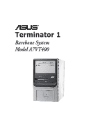
Terminator 1 Barebone System Model A7VT400 - Asus Terminator A7VT400 | Terminator A7VT400 User''s Manual for English - Page 2
Product warranty or service will not be extended if: (1) the product is repaired, modified or altered, unless such repair, modification of alteration is authorized in writing by ASUS; or (2) the serial number of the product is defaced or missing. ASUS PROVIDES THIS MANUAL "AS IS" WITHOUT WARRANTY - Asus Terminator A7VT400 | Terminator A7VT400 User''s Manual for English - Page 3
Table of contents Notices vi Safety information vii About this guide viii System package contents x Chapter 1: System introduction 1.1 Welcome 2-13 2.8.4 Standard interrupt assignments 2-14 2.8.5 IRQ assignments for this motherboard 2-14 2.9 Installing a CD-ROM drive 2-15 2.10 Installing a - Asus Terminator A7VT400 | Terminator A7VT400 User''s Manual for English - Page 4
2.14 Connecting external devices 2-23 Power supply specifications 2-24 2.14.1 Input Characteristics 2-24 2.14.2 Output Characteristics 2-24 2.14.3 Over-Voltage Protection (OVP 2-24 Chapter 3: Starting up 3.1 Installing an operating system 3-2 3.2 Support CD information 3-2 3.2.1 Running the - Asus Terminator A7VT400 | Terminator A7VT400 User''s Manual for English - Page 5
Memory configuration 5-15 5.4.3 Chipset configuration 5-16 5.4.4 PCIPnP 5-18 5.4.5 Onboard device configuration 5-19 5.4.6 USB configuration 5-21 5.5 Power Menu 5-22 5.5.1 APM configuration 5-23 5.5.2 Hardware monitor 5-26 5.6 Boot Menu 5-28 5.6.1 Boot Device Priority 5-28 5.6.2 Removable - Asus Terminator A7VT400 | Terminator A7VT400 User''s Manual for English - Page 6
. This equipment generates, uses and can radiate radio frequency energy and, if not installed and used in accordance with manufacturer's instructions, may cause harmful interference to radio communications. However, there is no guarantee that interference will not occur in a particular installation - Asus Terminator A7VT400 | Terminator A7VT400 User''s Manual for English - Page 7
connected. • If the power supply is broken, do not try to fix it by yourself. Contact a qualified service technician or your retailer on a stable surface. • If you encounter technical problems with the product, contact a qualified service technician or your retailer. Lithium-Ion Battery Warning C - Asus Terminator A7VT400 | Terminator A7VT400 User''s Manual for English - Page 8
About this guide Audience This guide provides general information and installation instructions about the ASUS Terminator 1 barebone system. This guide is intended for experienced users and integrators with hardware knowledge of personal computers. How this guide is organized This guide contains the - Asus Terminator A7VT400 | Terminator A7VT400 User''s Manual for English - Page 9
Conventions used in this guide W A R N I N G : Information to prevent injury to yourself when trying to complete a task. C A U T I O N : Information to prevent damage to the components when trying to complete a task. I M P O R T A N T : Instructions that you MUST follow to complete a task. N O T E : - Asus Terminator A7VT400 | Terminator A7VT400 User''s Manual for English - Page 10
. Item description 1 . A S U S T e r m i n a t o r 1 b a r e b o n e s y s t e m with • ASUS motherboard • 165 W PFC/non-PFC power supply unit • 2 x 5.25" drive bays • 1 x 3.5" hard disk drive bay • 4 x USB 2.0 ports 2. Cable • AC power cable and plug 3 . Support CD 4 . User guide 5 . Optional items - Asus Terminator A7VT400 | Terminator A7VT400 User''s Manual for English - Page 11
System introduction Chapter 1 This chapter gives a general description of the ASUS Terminator 1 A7VT400. The chapter lists the system features including introduction on the front and rear panel, and internal components. ASUS Terminator 1 A7VT400 - Asus Terminator A7VT400 | Terminator A7VT400 User''s Manual for English - Page 12
comes in a stylish mini-tower casing, and is powered by the ASUS motherboard that supports AMD Sempron™ processors. 1.2 Front panel The ASUS Terminator 1 A7VT400 barebone system is composed of the ASUS motherboard and a power supply unit in the ASUS TriOptix form factor chassis. The CD-ROM drive and - Asus Terminator A7VT400 | Terminator A7VT400 User''s Manual for English - Page 13
USB 2.0 devices such as a mouse, printer, scanner, camera, PDA, and others. 9 . H e a d p h o n e p o r t . This port connects a headphone with a stereo mini-plug. 1 0 . M i c r o p h o n e p o r t . This Mic (pink) port connects a microphone. ASUS Terminator 1 A7VT400 1-3 - Asus Terminator A7VT400 | Terminator A7VT400 User''s Manual for English - Page 14
1.3 Rear panel The system rear panel includes the power socket and several I/O ports that allow convenient connection of devices. 1 2 3 4 5 6 7 8 9 10 11 12 13 115V/230V Voltage selector 1 . G A M E / M I D I p o r t . This port connects a joystick or game pad - Asus Terminator A7VT400 | Terminator A7VT400 User''s Manual for English - Page 15
to the voltage supply in your area. If the voltage supply in your area is 100-127 V, set the switch to 115 V. If the voltage supply in your area is 200-240 V, set the switch to 230 V. Setting the switch to 115 V in a 230 V environment will seriously damage the system! ASUS Terminator 1 A7VT400 1-5 - Asus Terminator A7VT400 | Terminator A7VT400 User''s Manual for English - Page 16
of the available drive bays are pointed out. The system may come with either a PFC (Power Factor Correction) or non-PFC power supply. 3 1 4 5 2 6 7 1. Game/MIDI/COM1 extension module 2. Motherboard 3. Two 5.25" drive bays (Optional CD-ROM) 4. 3.5" HDD drive bay 5. 3.5" floppy drive bay (Optional - Asus Terminator A7VT400 | Terminator A7VT400 User''s Manual for English - Page 17
Basic installation Chapter 2 This chapter gives step-by-step instructions on how to install components into the barebone system. ASUS Terminator 1 A7VT400 - Asus Terminator A7VT400 | Terminator A7VT400 User''s Manual for English - Page 18
power supply case, before handling components to avoid damaging them due to static electricity. • Hold components by the edges to avoid touching the ICs on them. • Whenever you uninstall any component, place it on a grounded antistatic pad or in the bag that came with the component. The motherboard - Asus Terminator A7VT400 | Terminator A7VT400 User''s Manual for English - Page 19
panel edge, then push the inner chassis with your thumbs while pulling the panel with your other fingers. 3. While supporting the front panel with one hand, place your other hand on the top rear edge of the cover and carefully lift the cover from the chassis. Screw ASUS Terminator 1 A7VT400 2-3 - Asus Terminator A7VT400 | Terminator A7VT400 User''s Manual for English - Page 20
switch are attached to a metal module secured to the rear panel by a screw. Remove the screw to release the power socket module. Power socket module screw Power socket module You must release the power socket module from the rear panel before detaching the drive frame to avoid breaking the - Asus Terminator A7VT400 | Terminator A7VT400 User''s Manual for English - Page 21
3. Place your thumb on the right edge of the power socket module, then slide the module to the right until it is completely detached from the rear panel from the chassis when installing components. 5. Carefully lay the drive frame alongside the main chassis frame. ASUS Terminator 1 A7VT400 2-5 - Asus Terminator A7VT400 | Terminator A7VT400 User''s Manual for English - Page 22
2.5 Installing a CPU The motherboard comes with a surface mount 462-pin Zero Insertion Force (ZIF) socket CPU installation To install the CPU: 1. Locate the 462-pin ZIF socket on the motherboard. LOCK LEVER CPU NOTCH ® CPU socket 462 CPU NOTCH TO INNER CORNER AMD™ CPU 2-6 Chapter 2: - Asus Terminator A7VT400 | Terminator A7VT400 User''s Manual for English - Page 23
is in place, push down the socket lever to secure the CPU. The lever clicks on the side tab to indicate that it is locked. ASUS Terminator 1 A7VT400 2-7 - Asus Terminator A7VT400 | Terminator A7VT400 User''s Manual for English - Page 24
fan and heatsink assembly is an optional item in the Terminator 1 barebone system package. The processor requires a CPU fan and heatsink heatsink to avoid thermal problems. • Use only AMD-certified fan and heatsink assembly. • Make sure that you have installed the motherboard to the chassis before - Asus Terminator A7VT400 | Terminator A7VT400 User''s Manual for English - Page 25
and heatsink assembly. 4. Connect the CPU fan cable from the assembly to the fan connector labeled CPU_FAN1. Heatsink bracket Socket tabs CPU fan connector (CPU_FAN1) ASUS Terminator 1 A7VT400 2-9 - Asus Terminator A7VT400 | Terminator A7VT400 User''s Manual for English - Page 26
2.7 Installing system memory The motherboard comes with two Double Data Rate (DDR) Dual Inline Memory Module (DIMM) sockets. These sockets support up to 2 GB system memory using unbuffered ECC or non-ECC PC2700/PC2100/PC1600 DIMMs. 104 Pins 80 Pins ® 184-Pin DDR DIMM sockets DIMM2 - Asus Terminator A7VT400 | Terminator A7VT400 User''s Manual for English - Page 27
2.7.2 DIMM installation To install a DDR DIMM: 1. Locate the two DIMM sockets on the motherboard. 2. Unlock a socket by pressing the retaining clips outward. 3. Align a DIMM on the in only one direction. DO NOT force a DIMM into a socket to avoid damaging the DIMM. ASUS Terminator 1 A7VT400 2-11 - Asus Terminator A7VT400 | Terminator A7VT400 User''s Manual for English - Page 28
you buy an AGP card, make sure that you ask for one with 1.5V specification. Install only +1.5V AGP cards. The motherboard does not support 3.3V AGP cards. Make sure to unplug the power cord before adding or removing expansion cards. Failure to do so may cause you physical injury and damage the - Asus Terminator A7VT400 | Terminator A7VT400 User''s Manual for English - Page 29
the software settings. 1. Turn on the system and change the necessary BIOS settings, if any. See Chapter 5 for information on BIOS setup. 2. Install the software drivers for the expansion card. ASUS Terminator 1 A7VT400 2-13 - Asus Terminator A7VT400 | Terminator A7VT400 User''s Manual for English - Page 30
14* 9 Primary IDE Channel 15* 10 Secondary IDE Channel * These IRQs are usually available for ISA or PCI devices. 2.8.5 IRQ assignments for this motherboard PCI slot AGP slot USB 1.1 UHCI 1 USB 1.1 UHCI 1 USB 1.1 UHCI 1 USB 2.0 EHCI Onboard Audio Onboard LAN A B C - used - used - Asus Terminator A7VT400 | Terminator A7VT400 User''s Manual for English - Page 31
2.9 Installing a CD-ROM drive A CD-ROM drive is an optional item in this barebone system. Refer to the instructions in this section if you acquired a model without a CD-ROM. To install a CD-ROM drive: screws on each side of the bay. 5.25-inch drive bay CD-ROM screws ASUS Terminator 1 A7VT400 2-15 - Asus Terminator A7VT400 | Terminator A7VT400 User''s Manual for English - Page 32
5. Connect a power cable from the power supply to the power connector at the back of the CD-ROM ROM. Red stripe to Pin 1 Power cable (P1) 8. Connect the other end of the IDE ribbon cable to the secondary IDE connector (black connector labeled SEC_IDE) on the motherboard. 9. Connect the other end - Asus Terminator A7VT400 | Terminator A7VT400 User''s Manual for English - Page 33
until its screw holes align with the holes on the bay marked HDD. 4. Secure the drive with two screws on each side of the bay. ASUS Terminator 1 A7VT400 HDD screws 2-17 - Asus Terminator A7VT400 | Terminator A7VT400 User''s Manual for English - Page 34
5. Connect a power cable from the power supply to the power connector at the back of the HDD. Use the cable with the the cable with Pin 1 on the IDE interface. Red stripe to Pin 1 IDE ribbon cable Power cable (P3) 7. Connect the other end of the IDE ribbon cable to the primary IDE connector (blue connector - Asus Terminator A7VT400 | Terminator A7VT400 User''s Manual for English - Page 35
Reset Ground PANEL HDLED RESET SMI PWRBTN* * Requires an ATX power supply. • Connect the power switch and power LED cables to their respective leads in the PANEL connector on the motherboard. • Connect the H D D L E D cable to the 2-pin lead marked HDLED. ASUS Terminator 1 A7VT400 2-19 - Asus Terminator A7VT400 | Terminator A7VT400 User''s Manual for English - Page 36
. USB T: Port0 B: Port1 J1 UAEX HPHONE1 J2 MIC ® Connect to MIC_LOUT connector on the motherboard Connect to USB34 connector on the motherboard Connector locations on the motherboard MIC_LOUT connector (for Microphone/ Line Out cable) USB34 USB56 2-20 Chapter 2: Basic installation - Asus Terminator A7VT400 | Terminator A7VT400 User''s Manual for English - Page 37
perfectly to the chassis edge. 3. Turn the chassis upright. 4. Place the cover over the chassis leaving about two inches from the rear panel. Protruding tab ASUS Terminator 1 A7VT400 2-21 - Asus Terminator A7VT400 | Terminator A7VT400 User''s Manual for English - Page 38
5. Fit the rail tabs on the sides and bottom of the cover to the edges of the chassis. Rail tabs 6. Push the cover towards the rear until it fits. The locking tab snaps into the hole on the chassis indicating that the cover is in place. Locking tab Locking tab hole Firmly push the cover to ensure - Asus Terminator A7VT400 | Terminator A7VT400 User''s Manual for English - Page 39
2.13 Connecting external devices The figure below shows the specific connectors and devices that you can connect to the rear panel ports. Serial PS/2 KB VGA Line Out Line In Mic RJ-45 Game/ MIDI PS/2 Mouse Parallel AC USB ASUS Terminator 1 A7VT400 2-23 - Asus Terminator A7VT400 | Terminator A7VT400 User''s Manual for English - Page 40
10% +10% -5% +5% -5% +5% Ripple Max 50mVp-p 120mVp-p 120mVp-p 50mVp-p 50mVp-p 2.14.3 Over-Voltage Protection (OVP) Output Voltage +5 V +12 V +3.3 V Maximum Voltage 6.5 V 15.6 V 4.3 V The power supply will shut down and latch off for shorting +5V, +12V, -12V, or +3.3V. By shorting +5VSB, the - Asus Terminator A7VT400 | Terminator A7VT400 User''s Manual for English - Page 41
Starting up Chapter 3 This chapter helps you power up your system and install drivers and utilities that came with the support CD. ASUS Terminator 1 A7VT400 - Asus Terminator A7VT400 | Terminator A7VT400 User''s Manual for English - Page 42
contains useful software and several utility drivers that enhance the motherboard features. The contents of the support CD are subject to change at any time without notice. Visit the ASUS website for updates. 3.2.1 Running the support CD To begin using the support CD, simply insert the CD into - Asus Terminator A7VT400 | Terminator A7VT400 User''s Manual for English - Page 43
keep your computer at a healthy operating condition. ASUS Update This item installs the ASUS Update. This program allows you to download the latest version of the BIOS from the ASUS website. Microsoft® Direct X Driver This item installs the Microsoft® Direct X driver. ASUS Terminator 1 A7VT400 3-3 - Asus Terminator A7VT400 | Terminator A7VT400 User''s Manual for English - Page 44
. ADOBE Acrobat Reader This item installs the Adobe Acrobat® Reader®. The Acrobat Reader software is for viewing files saved in Portable Document Format (PDF). ASUS Screen Saver This item installs the ASUS screen saver. 3.2.3 ASUS Contact information Click the C o n t a c t tab to display the - Asus Terminator A7VT400 | Terminator A7VT400 User''s Manual for English - Page 45
to display the specified information. Motherboard Info Displays the general specifications of the motherboard. The screen image below is for general reference only. The support CD will automatically detect the motherboard information and display it on your screen. ASUS Terminator 1 A7VT400 3-5 - Asus Terminator A7VT400 | Terminator A7VT400 User''s Manual for English - Page 46
Browse this CD Displays the support CD contents in graphical format. Technical support form Displays the ASUS Technical Support Request Form that you have to fill out when requesting technical support. Filelist Displays the contents of the support CD and a brief description of each in text format. - Asus Terminator A7VT400 | Terminator A7VT400 User''s Manual for English - Page 47
t a r t button, point to P r o g r a m s, and then A S U S U t i l i t y, and then click P r o b e V x . x x. The PC Probe icon appears on the taskbar system tray indicating that ASUS PC Probe is running. Clicking the icon allows you to see the status of your PC. ASUS Terminator 1 A7VT400 3-7 - Asus Terminator A7VT400 | Terminator A7VT400 User''s Manual for English - Page 48
Using ASUS PC Probe Monitoring Monitor Summary Shows a summary of the items being monitored. Temperature Monitor Shows the PC temperature. Temperature Warning threshold adjustment (Move the slider - Asus Terminator A7VT400 | Terminator A7VT400 User''s Manual for English - Page 49
predefined threshold. Hard Drives Shows the used and free space of the PC's hard disk drives and the file allocation table or file system used. ASUS Terminator 1 A7VT400 3-9 - Asus Terminator A7VT400 | Terminator A7VT400 User''s Manual for English - Page 50
pertinent to the PC, such as CPU type, CPU speed, and internal/external frequencies, and memory size. Utility Lets you run programs outside of the ASUS Probe modules. To run a program, click E x e c u t e P r o g r a m. This feature is currently unavailable. 3-10 Chapter3: Starting up - Asus Terminator A7VT400 | Terminator A7VT400 User''s Manual for English - Page 51
a network or an Internet Service Provider (ISP). To use the ASUS Update: 1. Launch the utility from your Windows Start menu: Programs/AsusUpdate Vx.xx.xx/AsusUpdate The ASUS Update initial screen appears. 2. Select your desired update method, then click N e x t. ASUS Terminator 1 A7VT400 3-11 - Asus Terminator A7VT400 | Terminator A7VT400 User''s Manual for English - Page 52
updating/ downloading from the Internet, select the ASUS FTP site nearest you to avoid network traffic, or choose Auto Select. Click N e x t. 4. From the FTP site, select the BIOS version that you wish to download. Click N e x t. 5. Follow the instructions on the succeeding screens to complete the - Asus Terminator A7VT400 | Terminator A7VT400 User''s Manual for English - Page 53
Motherboard info Chapter 4 This chapter gives information about the motherboard that came with the system.This chapter includes the motherboard layout, jumper settings, and connector locations. ASUS Terminator T1 A7VT400 - Asus Terminator A7VT400 | Terminator A7VT400 User''s Manual for English - Page 54
4.1 Introduction The ASUS motherboard comes already installed in the ASUS Terminator 1 A7VT400 barebone system. This chapter provides technical information about the motherboard for future upgrades or system reconfiguraiton. 4.2 Motherboard layout PS/2 T:Mouse B:Keyboard VGA IOC_MB ATX12V 23cm - Asus Terminator A7VT400 | Terminator A7VT400 User''s Manual for English - Page 55
power to CPU, DRAM in slow refresh, power supply in reduced power mode). The USBPWR12 jumper is for the rear USB ports. The USBPWR34 and USBPWR56 jumpers are for the internal USB connectors that you can connect to additional USB ports. • The motherboard 5VSB (Default) ASUS Terminator T1 A7VT400 4-3 - Asus Terminator A7VT400 | Terminator A7VT400 User''s Manual for English - Page 56
RAM in CMOS. You can clear the CMOS memory of date, time, and system setup parameters by erasing the CMOS RTC RAM data. The onboard button cell battery powers the RAM RTC RAM: 1. Turn OFF the computer and unplug the power cord Re-install the battery. 5. Plug the power cord and turn ON the computer. - Asus Terminator A7VT400 | Terminator A7VT400 User''s Manual for English - Page 57
. If your CPU FSB frequency is 133/166/200 MHz, set the jumper to 1-2. ® External frequency selection FSB 12 23 133/166/200 100 (Default) ASUS Terminator T1 A7VT400 4-5 - Asus Terminator A7VT400 | Terminator A7VT400 User''s Manual for English - Page 58
133/100/66 signal cables. The Ultra DMA 133/100/66 signal cable has three connectors: a blue connector for the primary IDE connector on the motherboard, a black connector for an Ultra DMA 133/100/66 IDE slave device (optical drive/hard disk drive), and a gray connector for an Ultra DMA 133 - Asus Terminator A7VT400 | Terminator A7VT400 User''s Manual for English - Page 59
Floppy disk drive connector (34-1 pin FLOPPY) This connector supports the provided floppy drive ribbon cable. After connecting one end to the motherboard, connect the other end to the floppy drive. (Pin (White) Right Audio Channel Ground CD (Black) Left Audio Channel ASUS Terminator T1 A7VT400 4-7 - Asus Terminator A7VT400 | Terminator A7VT400 User''s Manual for English - Page 60
12V) These connectors are for ATX power supply plugs. The plugs from the power supply are designed to fit these connectors supports legacy AC'97 audio standard. MIC_LOUT Head set Left channel Head set Right channel GND 1 1 ® MIC PWR MIC Signal Front panel audio connector 4-8 Chapter 4: Motherboard - Asus Terminator A7VT400 | Terminator A7VT400 User''s Manual for English - Page 61
may damage the motherboard components. These are not jumpers! Do not place jumper caps on the fan connectors! 7. IO extension module connector (22-pin IOC_MB) This connector is for the CGAEX extension module. ® CGAEX extension module COM1 GAME ® CGAEX IOC_DC ASUS Terminator T1 A7VT400 4-9 - Asus Terminator A7VT400 | Terminator A7VT400 User''s Manual for English - Page 62
pin PANEL) This connector supports several chassis-mounted functions. PLED SPEAKER +5VSB PLED +5V Ground Ground Speaker +5 V MLED ExtSMI# Ground PWR Ground Reset Ground ® System panel connector HDLED RESET SMI PWRBTN* * Requires an ATX power supply. 4-10 Chapter 4: Motherboard information - Asus Terminator A7VT400 | Terminator A7VT400 User''s Manual for English - Page 63
connector is for the system power button. Pressing the power button turns the system on or puts the system in sleep or soft-off mode depending on the BIOS settings. Pressing the power switch for more than four seconds while the system is ON turns the system OFF. ASUS Terminator T1 A7VT400 4-11 - Asus Terminator A7VT400 | Terminator A7VT400 User''s Manual for English - Page 64
4-12 Chapter 4: Motherboard information - Asus Terminator A7VT400 | Terminator A7VT400 User''s Manual for English - Page 65
BIOS information Chapter 5 This chapter tells how to change system settings through the BIOS Setup menus. It includes detailed descriptions of the BIOS parameters. ASUS Terminator 1 A7VT400 - Asus Terminator A7VT400 | Terminator A7VT400 User''s Manual for English - Page 66
motherboard BIOS using the ASUS Update or AFLASH utilities. • Visit the ASUS website and download the latest BIOS file for this motherboard using the ASUS Insert a 1.44 MB floppy disk when prompted. Follow the succeeding screen instructions to complete the process. 5-2 Chapter 5: BIOS information - Asus Terminator A7VT400 | Terminator A7VT400 User''s Manual for English - Page 67
r t. 2. Copy the original (or the latest) motherboard BIOS to the bootable floppy disk. 5.1.2 Updating the BIOS these instructions to support CD to the floppy disk with the latest BIOS file. 3. Boot the system in DOS mode using the bootable floppy disk you created earlier. ASUS Terminator 1 A7VT400 - Asus Terminator A7VT400 | Terminator A7VT400 User''s Manual for English - Page 68
disk containing the new BIOS file and the Award BIOS Flash Utility. 5. At the prompt, type a w d f l a s h then press AwardBIOS Flash Utility for ASUS B107A (C) Phoenix Technologies Ltd. All Rights Reserved . The Award For KM400A-8235M-6A6LYA0AC BIOS Flash Utility screen Flash Type - SST - Asus Terminator A7VT400 | Terminator A7VT400 User''s Manual for English - Page 69
OK 111122223333 No Update 111122223333 Write Fail Warning: Don't Turn Off Power Or Reset System! Do not turn off or reset the system Press to Continue restart the system. 111122223333 Write OK 111122223333 No Update 111122223333 Write Fail F1 Reset ASUS Terminator 1 A7VT400 5-5 - Asus Terminator A7VT400 | Terminator A7VT400 User''s Manual for English - Page 70
... 3. Insert a floppy disk that contains the original, or the latest, BIOS file for this motherboard (A7VT400.BIN). If the BIOS file that you downloaded from the ASUS website has a different filename (e.g. A7VT400_1001.001). Rename it to A 7 V T 4 0 0 . B I N. The BIOS update process continues - Asus Terminator A7VT400 | Terminator A7VT400 User''s Manual for English - Page 71
the support CD that comes with the motherboard package. ASUS Update requires an Internet connection either through a network or an Internet Service Provider (ISP). Go to section "3.3.2 ASUS Update" for details on how to update the motherboard BIOS using ASUS Update. ASUS Terminator 1 A7VT400 5-7 - Asus Terminator A7VT400 | Terminator A7VT400 User''s Manual for English - Page 72
motherboard supports a programmable Flash ROM that you can update using the provided utility described in section "5.1 Managing and updating your BIOS." Use the BIOS Setup program when you are installing a motherboard the power management RAM of the Flash ROM. The Flash ROM on the motherboard - Asus Terminator A7VT400 | Terminator A7VT400 User''s Manual for English - Page 73
Use this menu to enable and make changes to the advanced features. POWER Use this menu to configure and enable Power Management features. BOOT Use this menu to configure the default system device current screen to its Setup Defaults Saves changes and exits Setup ASUS Terminator 1 A7VT400 5-9 - Asus Terminator A7VT400 | Terminator A7VT400 User''s Manual for English - Page 74
General help In addition to the Item Specific Help window, the BIOS setup program also provides a General Help screen. You may launch this screen from any menu by simply pressing . The General Help screen lists the legend keys and their corresponding functions. Saving changes and exiting the - Asus Terminator A7VT400 | Terminator A7VT400 User''s Manual for English - Page 75
.] [1.44M, 3.5 in.] [2.88M, 3.5 in.] 5.3.4 Installed Memory [xxx MB] This field automatically displays the amount of conventional memory detected by the system during the boot process. ASUS Terminator 1 A7VT400 5-11 - Asus Terminator A7VT400 | Terminator A7VT400 User''s Manual for English - Page 76
] to manually enter the IDE hard disk drive parameters. Refer to the next section for details. Before attempting to configure a hard disk drive, make sure you have the correct configuration information supplied by the drive manufacturer. Incorrect settings may cause the system to fail to recognize - Asus Terminator A7VT400 | Terminator A7VT400 User''s Manual for English - Page 77
cause the system to malfunction. CPU Configuration Memory Configuration Chipset PCIPnP Onboard Device Configuration USB Configuration Select Menu Item Specific Help Press [Enter] to Set. ASUS Terminator 1 A7VT400 5-13 - Asus Terminator A7VT400 | Terminator A7VT400 User''s Manual for English - Page 78
5.4.1 CPU configuration The items in this menu show the CPU-related information auto-detected by the BIOS. CPU Configuration CPU Type CPU Speed Cache RAM Current FSB Frequency AMD Athlon (tm) 1000 MHz 256 K 100 MHz Select Menu Item Specific Help 5-14 Chapter 5: BIOS information - Asus Terminator A7VT400 | Terminator A7VT400 User''s Manual for English - Page 79
). Select [Auto by SPD] for automatic DRAM clock detection. Select [Manual] to set the DRAM Timing manually. Select [Safe] to set the DRAM timing to safe value. Configuration options: [Auto by SPD 2T] [3T] tWTR [2T] Sets the tWTR time. Configuration options: [1T] [2T] ASUS Terminator 1 A7VT400 5-15 - Asus Terminator A7VT400 | Terminator A7VT400 User''s Manual for English - Page 80
5.4.3 Chipset configuration The items in this menu show the chipset configuration settings. Select an item then press to display a pop-up menu with the configuration options. Chipset AGP Display Switch [Auto] Init Display First [PCI slot] AGP Bridge Configuration Select Menu Item - Asus Terminator A7VT400 | Terminator A7VT400 User''s Manual for English - Page 81
AGP Mode [8X] This motherboard supports the AGP 8X interface that enables enhanced graphics performance with high bandwidths of up to 2.21 GB/s. AGP 8X you share with VGA, the less memory space is left for other system devices. Configuration options: [16M] [32M] [64M] ASUS Terminator 1 A7VT400 5-17 - Asus Terminator A7VT400 | Terminator A7VT400 User''s Manual for English - Page 82
boot and Plug and Play devices. When set to [Manual], you can assign the available IRQ resources to the PCI devices. Configuration options: [Auto] [Manual] When the item R e s o u r properly. Setting this field to [Enabled] corrects this problem. If you are using standard VGA cards, leave this - Asus Terminator A7VT400 | Terminator A7VT400 User''s Manual for English - Page 83
you disable this field, the Parallel Port Mode and ECP DMA Select configurations are not available. Configuration options: [Disabled] [378/ IRQ7] [278/IRQ5] [3BC/IRQ7] ASUS Terminator 1 A7VT400 5-19 - Asus Terminator A7VT400 | Terminator A7VT400 User''s Manual for English - Page 84
Parallel Port Mode [ECP+EPP] Allows you to set the operation mode of the parallel port. Configuration options: [SPP] [EPP] [ECP] [ECP+EPP] EPP Mode Select [EPP1.7] Allows you to select the EPP mode. This items becomes configurable only if the P a r a l l e l P o r t M o d e is set to [EPP] or [ECP+ - Asus Terminator A7VT400 | Terminator A7VT400 User''s Manual for English - Page 85
USB support in the BIOS to turn on automatically when you install high speed USB devices. Configuration options: [Enabled] Disabled] USB Legacy Support [Enabled] Allows you to enable or disable support for legacy USB devices. Configuration options: [Enabled] Disabled] ASUS Terminator 1 A7VT400 - Asus Terminator A7VT400 | Terminator A7VT400 User''s Manual for English - Page 86
menu allows you to reduce power consumption. This feature turns off the video display and shuts down the hard disk after a period of inactivity. ACPI Suspend Type ACPI APIC Support APM Configuration Hardware Monitor [S1 & S3] [Enabled] Select Menu Item Specific Help ACPI Suspend Type [S1 & S3 - Asus Terminator A7VT400 | Terminator A7VT400 User''s Manual for English - Page 87
[Enabled] Power Up On PCI Devices [Disabled] When set to [Enabled], this parameter allows you to turn on the system through a PCI modem. This feature requires an ATX power supply that provides at least 1A on the +5VSB lead. Configuration options: [Disabled] [Enabled] ASUS Terminator 1 A7VT400 5-23 - Asus Terminator A7VT400 | Terminator A7VT400 User''s Manual for English - Page 88
the first try. Turning an external modem off and then back on while the computer is off causes an initialization string that turns the system power on. Power On By RTC Alarm [Disabled] Allows you to enable or disable RTC to generate an event. When this item is enabled, you can set - Asus Terminator A7VT400 | Terminator A7VT400 User''s Manual for English - Page 89
not to reboot the system after power interruptions. [Power Off] leaves your system off, [Power On] reboots the system, and [Last State] sets the system back to the state it was before the power interruption. Configuration options: [Power Off] [Power On] [Last State] ASUS Terminator 1 A7VT400 5-25 - Asus Terminator A7VT400 | Terminator A7VT400 User''s Manual for English - Page 90
Fan Function [Disabled] This item allows you to enable or disable the ASUS Q-Fan feature that smartly adjusts the CPU fan speed for more efficient xxxoF ] The onboard hardware monitor automatically detects and displays the power supply and CPU temperatures in these fields. Chassis Fan Speed [xxxxRPM] - Asus Terminator A7VT400 | Terminator A7VT400 User''s Manual for English - Page 91
VCORE Voltage, +3.3V Voltage, +5V Voltage, +12V Voltage The onboard hardware monitor automatically detects the voltage output through the onboard voltage regulators. ASUS Terminator 1 A7VT400 5-27 - Asus Terminator A7VT400 | Terminator A7VT400 User''s Manual for English - Page 92
5.6 Boot Menu The Boot menu items allow you to change the system boot settings. Select an item then press to display a pop-up menu with the configuration options. Boot Device Priority Removable Drives Hard Drisk Drives CDROM Drives Boot Settings Configuration Security Select Menu Item - Asus Terminator A7VT400 | Terminator A7VT400 User''s Manual for English - Page 93
it up, or to move it down the list. Press to exit this menu. 5.6.3 Hard disk drives Hard Disk Drives 1. Bootable Add-in Cards ASUS Terminator 1 A7VT400 Select Menu Item Specific Help Use or arrow to select a device, then press to move it up, or to move it down the - Asus Terminator A7VT400 | Terminator A7VT400 User''s Manual for English - Page 94
5.6.4 CD-ROM drives CDROM Drives Select Menu 1. Pri. Slave: Pioneer CD-ROM ATAPI Model Item Specific Help Use or arrow to select a device, then press to move it up, or to move it down the list. Press to exit this menu. 5.6.5 Boot settings configuration Boot Settings - Asus Terminator A7VT400 | Terminator A7VT400 User''s Manual for English - Page 95
Up Num-Lock Status [On] Allows you to select the power-on state for the NumLock. Configuration options: [On] [Off [OS2] only when you are using an OS2 operating system with greater than 64MB RAM. Otherwise, set to [Non-OS2]. Configuration options: [Non-OS2] [OS2] Key] ASUS Terminator 1 A7VT400 5-31 - Asus Terminator A7VT400 | Terminator A7VT400 User''s Manual for English - Page 96
5.6.6 Security Security Supervisor Password User Password Password Check Clear Clear [Setup] Select Menu Item Specific Help Supervisor password controls full access, to change password. Supervisor Password [Clear] User Password [Clear] These fields allow you to set passwords. To set a - Asus Terminator A7VT400 | Terminator A7VT400 User''s Manual for English - Page 97
(RTC) RAM. The RAM data containing the password information is powered by the onboard button cell battery. If you need to erase the CMOS RAM, refer to section "4.3 Jumpers" for instructions. Password press , to cancel the command and return to the Exit menu ASUS Terminator 1 A7VT400 5-33 - Asus Terminator A7VT400 | Terminator A7VT400 User''s Manual for English - Page 98
. Select [Yes] to load default values. Select Exit Saving Changes or make other changes before saving the values to the non-volatile RAM. Discard Changes This option allows you to discard the selections you made and restore the previously saved values. After selecting this option, a confirmation
-
 1
1 -
 2
2 -
 3
3 -
 4
4 -
 5
5 -
 6
6 -
 7
7 -
8
-
9
-
10
-
11
-
12
-
13
-
14
-
15
-
16
-
17
-
18
-
19
-
20
-
21
-
22
-
23
-
24
-
25
-
26
-
27
-
28
-
29
-
30
-
31
-
32
-
33
-
34
-
35
-
36
-
37
-
38
-
39
-
40
-
41
-
42
-
43
-
44
-
45
-
46
-
47
-
48
-
49
-
50
-
51
-
52
-
53
-
54
-
55
-
56
-
57
-
58
-
59
-
60
-
61
-
62
-
63
-
64
-
65
-
66
-
67
-
68
-
69
-
70
-
71
-
72
-
73
-
74
-
75
-
76
-
77
-
78
-
79
-
80
-
81
-
82
-
83
-
84
-
85
-
86
-
87
-
88
-
89
-
90
-
91
-
92
-
93
-
94
-
95
-
96
-
97
-
98
 |
 |
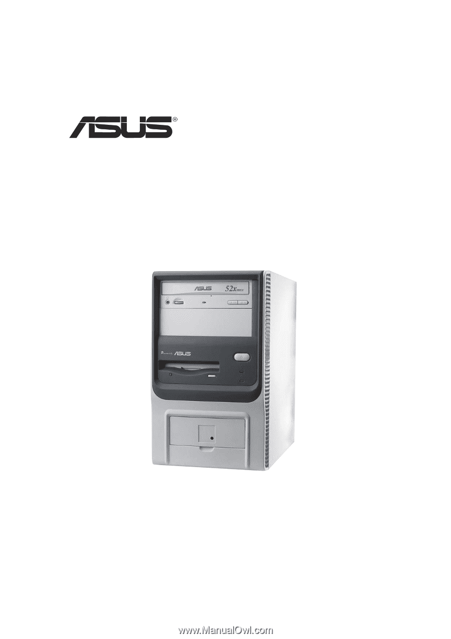
Terminator 1
Barebone System
Model A7VT400