Asus Terminator A7VT400 Terminator A7VT400 User''s Manual for English - Page 13
USB 2.0 ports. These Universal Serial Bus 2.0 USB 2.0 ports are
 |
View all Asus Terminator A7VT400 manuals
Add to My Manuals
Save this manual to your list of manuals |
Page 13 highlights
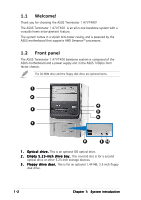
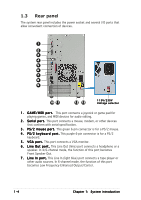
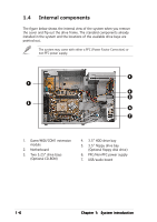
4 . P o w e r b u t t o n . Press this button to turn the system on. 5 . P o w e r L E D . This LED lights up to indicate that the system is ON. 6 . H D D L E D . This LED lights up when data is being read from or written to the hard disk drive. 7 . F r o n t p a n e l I / O d o o r . Flip up this door to show the front panel input/output ports. 8 . U S B 2 . 0 p o r t s . These Universal Serial Bus 2.0 (USB 2.0) ports are available for connecting USB 2.0 devices such as a mouse, printer, scanner, camera, PDA, and others. 9 . H e a d p h o n e p o r t . This port connects a headphone with a stereo mini-plug. 1 0 . M i c r o p h o n e p o r t . This Mic (pink) port connects a microphone. ASUS Terminator 1 A7VT400 1-3
-
 1
1 -
2
-
3
-
4
-
5
-
6
-
7
-
 8
8 -
 9
9 -
 10
10 -
 11
11 -
 12
12 -
 13
13 -
 14
14 -
 15
15 -
 16
16 -
 17
17 -
 18
18 -
19
-
20
-
21
-
22
-
23
-
24
-
25
-
26
-
27
-
28
-
29
-
30
-
31
-
32
-
33
-
34
-
35
-
36
-
37
-
38
-
39
-
40
-
41
-
42
-
43
-
44
-
45
-
46
-
47
-
48
-
49
-
50
-
51
-
52
-
53
-
54
-
55
-
56
-
57
-
58
-
59
-
60
-
61
-
62
-
63
-
64
-
65
-
66
-
67
-
68
-
69
-
70
-
71
-
72
-
73
-
74
-
75
-
76
-
77
-
78
-
79
-
80
-
81
-
82
-
83
-
84
-
85
-
86
-
87
-
88
-
89
-
90
-
91
-
92
-
93
-
94
-
95
-
96
-
97
-
98
 |
 |

ASUS Terminator 1 A7VT400
ASUS Terminator 1 A7VT400
ASUS Terminator 1 A7VT400
ASUS Terminator 1 A7VT400
ASUS Terminator 1 A7VT400
1-3
1-3
1-3
1-3
1-3
4.
4.
4.
4.
4.
Power button.
Power button.
Power button.
Power button.
Power button. Press this button to turn the system on.
5.
5.
5.
5.
5.
Power LED.
Power LED.
Power LED.
Power LED.
Power LED. This LED lights up to indicate that the system is ON.
6.
6.
6.
6.
6.
HDD LED.
HDD LED.
HDD LED.
HDD LED.
HDD LED. This LED lights up when data is being read from or written
to the hard disk drive.
7.
7.
7.
7.
7.
Front panel I/O door.
Front panel I/O door.
Front panel I/O door.
Front panel I/O door.
Front panel I/O door. Flip up this door to show the front panel
input/output ports.
8.
8.
8.
8.
8.
USB 2.0 ports.
USB 2.0 ports.
USB 2.0 ports.
USB 2.0 ports.
USB 2.0 ports. These Universal Serial Bus 2.0 (USB 2.0) ports are
available for connecting USB 2.0 devices such as a mouse, printer,
scanner, camera, PDA, and others.
9.
9.
9.
9.
9.
Headphone port.
Headphone port.
Headphone port.
Headphone port.
Headphone port. This port connects a headphone with a stereo
mini-plug.
10.
10.
10.
10.
10. Microphone port.
Microphone port.
Microphone port.
Microphone port.
Microphone port. This Mic (pink) port connects a microphone.