Asus Terminator A7VT400 Terminator A7VT400 User''s Manual for English - Page 54
Introduction, Motherboard layout
 |
View all Asus Terminator A7VT400 manuals
Add to My Manuals
Save this manual to your list of manuals |
Page 54 highlights
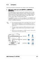
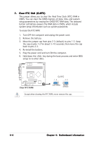
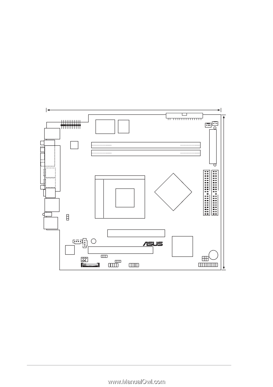
4.1 Introduction The ASUS motherboard comes already installed in the ASUS Terminator 1 A7VT400 barebone system. This chapter provides technical information about the motherboard for future upgrades or system reconfiguraiton. 4.2 Motherboard layout PS/2 T:Mouse B:Keyboard VGA IOC_MB ATX12V 23cm (9.06in) Super Flash I/O BIOS FLOPPY CHA_FAN CPU_FAN ATXPWR DDR DIMM2 (64/72-bit, 184-pin module) DDR DIMM1 (64/72-bit, 184-pin module) PARALLEL PORT Socket 462 Line Out Line In Mic In RJ-45 LANLED USB T:Port2 B:Port1 USBPWR12 CD4 AD1888 AUX MIC_LOUT BATTERY VIA KM400A PRI_IDE SEC_IDE Accelerated Graphics Port (AGP) SB_PWR ® PCI1 USBPWR34 USBPWR56 USB34 USB56 VIA VT8235M BUZZER FSB CLRTC PANEL 22.4cm (8.82in) 4-2 Chapter 4: Motherboard information
-
 1
1 -
2
-
3
-
4
-
5
-
6
-
7
-
8
-
9
-
10
-
11
-
12
-
13
-
14
-
15
-
16
-
17
-
18
-
19
-
20
-
21
-
22
-
23
-
24
-
25
-
26
-
27
-
28
-
29
-
30
-
31
-
32
-
33
-
34
-
35
-
36
-
37
-
38
-
39
-
40
-
41
-
42
-
43
-
44
-
45
-
46
-
47
-
48
-
 49
49 -
 50
50 -
 51
51 -
 52
52 -
 53
53 -
 54
54 -
 55
55 -
 56
56 -
 57
57 -
 58
58 -
 59
59 -
60
-
61
-
62
-
63
-
64
-
65
-
66
-
67
-
68
-
69
-
70
-
71
-
72
-
73
-
74
-
75
-
76
-
77
-
78
-
79
-
80
-
81
-
82
-
83
-
84
-
85
-
86
-
87
-
88
-
89
-
90
-
91
-
92
-
93
-
94
-
95
-
96
-
97
-
98
 |
 |
4-2
4-2
4-2
4-2
4-2
Chapter 4:
Motherboard information
Chapter 4:
Motherboard information
Chapter 4:
Motherboard information
Chapter 4:
Motherboard information
Chapter 4:
Motherboard information
4.1
Introduction
The ASUS motherboard comes already installed in the ASUS Terminator 1
A7VT400 barebone system. This chapter provides technical information
about the motherboard for future upgrades or system reconfiguraiton.
4.2
Motherboard layout
23cm (9.06in)
CPU_FAN
VIA
KM400A
CHA_FAN
FLOPPY
AD1888
PANEL
USB34
USBPWR12
fi
IOC_MB
DDR DIMM2 (64/72-bit, 184-pin module)
PCI1
Super
I/O
Flash
BIOS
22.4cm (8.82in)
PS/2
T:Mouse
B:Keyboard
RJ-45
USB
T:Port2
B:Port1
DDR DIMM1 (64/72-bit, 184-pin module)
PRI_IDE
ATX12V
LANLED
BUZZER
VIA
VT8235M
Socket 462
CLRTC
SEC_IDE
USB56
USBPWR34
Accelerated Graphics Port (AGP)
PARALLEL PORT
VGA
Mic
In
Line
In
Line
Out
ATXPWR
USBPWR56
CD4
AUX
SB_PWR
FSB
BATTERY
MIC_LOUT