Asus Terminator A7VT400 Terminator A7VT400 User''s Manual for English - Page 32
the CD-ROM.
 |
View all Asus Terminator A7VT400 manuals
Add to My Manuals
Save this manual to your list of manuals |
Page 32 highlights
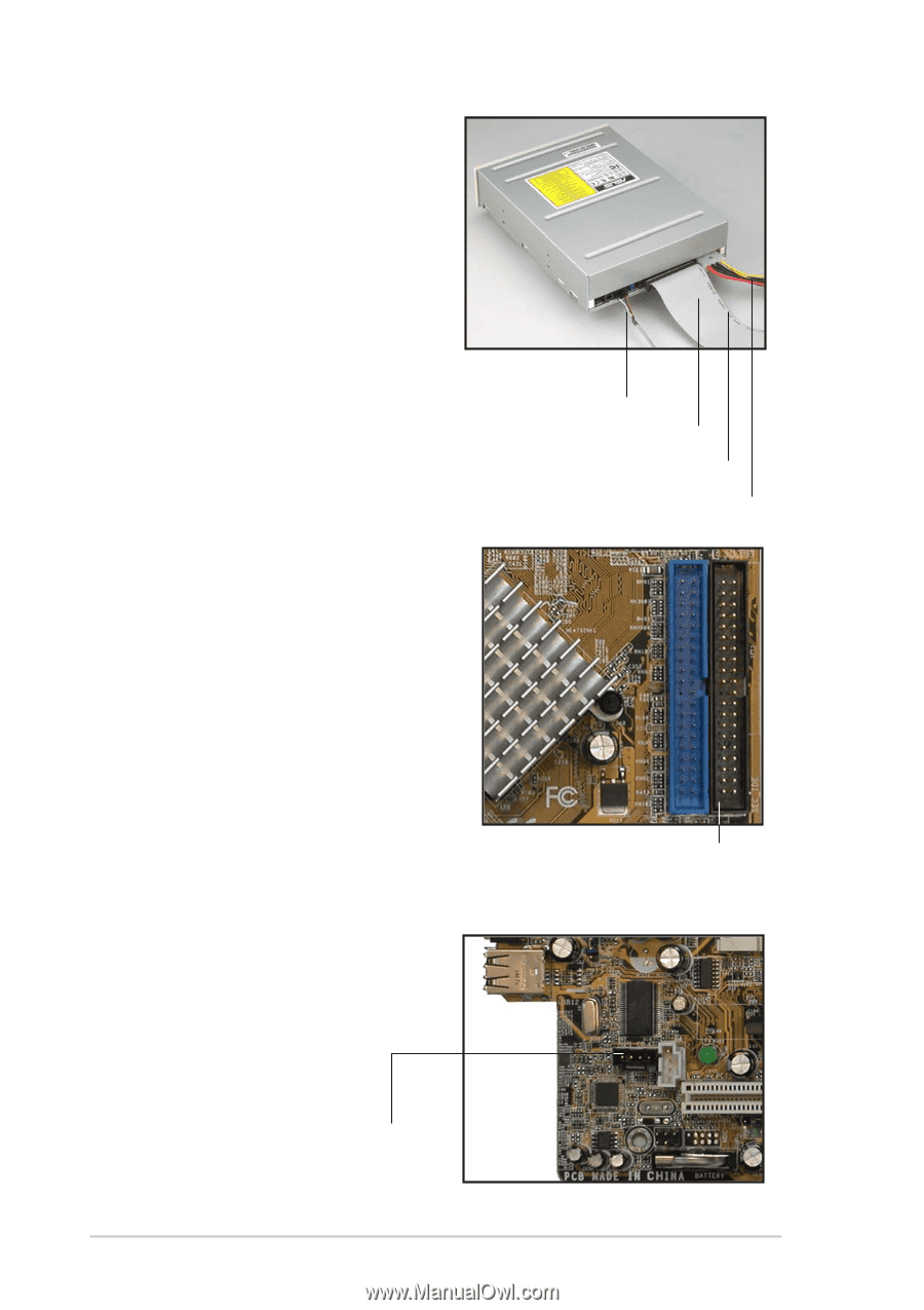
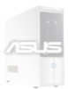
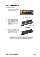
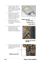
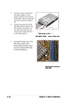
5. Connect a power cable from the power supply to the power connector at the back of the CD-ROM. Use the cable with the white connector labeled P1. 6. Connect one end of the IDE ribbon cable to the IDE interface at the back of the CD-ROM, matching the red stripe on the cable with Pin 1 on the IDE interface. 7. Connect one end of the CD-ROM audio cable CD-ROM audio cable to the IDE ribbon cable 4-pin connector at the back of the CD-ROM. Red stripe to Pin 1 Power cable (P1) 8. Connect the other end of the IDE ribbon cable to the secondary IDE connector (black connector labeled SEC_IDE) on the motherboard. 9. Connect the other end of the audio cable to the black 4-pin connector labeled CD on the motherboard. Secondary IDE connector (SEC_IDE) CD-ROM connector (CD) 2-16 Chapter 2: Basic installation
-
 1
1 -
2
-
3
-
4
-
5
-
6
-
7
-
8
-
9
-
10
-
11
-
12
-
13
-
14
-
15
-
16
-
17
-
18
-
19
-
20
-
21
-
22
-
23
-
24
-
25
-
26
-
 27
27 -
 28
28 -
 29
29 -
 30
30 -
 31
31 -
 32
32 -
 33
33 -
 34
34 -
 35
35 -
 36
36 -
 37
37 -
38
-
39
-
40
-
41
-
42
-
43
-
44
-
45
-
46
-
47
-
48
-
49
-
50
-
51
-
52
-
53
-
54
-
55
-
56
-
57
-
58
-
59
-
60
-
61
-
62
-
63
-
64
-
65
-
66
-
67
-
68
-
69
-
70
-
71
-
72
-
73
-
74
-
75
-
76
-
77
-
78
-
79
-
80
-
81
-
82
-
83
-
84
-
85
-
86
-
87
-
88
-
89
-
90
-
91
-
92
-
93
-
94
-
95
-
96
-
97
-
98
 |
 |