Asus Terminator A7VT400 Terminator A7VT400 User''s Manual for English - Page 62
System panel connector
 |
View all Asus Terminator A7VT400 manuals
Add to My Manuals
Save this manual to your list of manuals |
Page 62 highlights
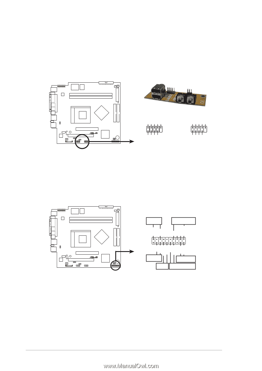
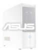
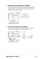
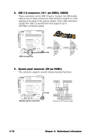
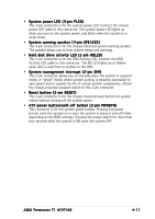
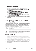
8 . USB 2.0 connectors (10-1 pin USB34, USB56) These connectors are for USB 2.0 ports. Connect the USB module cable to any of these connectors, then install the module to a slot opening at the back of the system chassis. These USB connectors comply with USB 2.0 specification that supports up to 480 Mbps connection speed. USB Power USBP2- USBP2+ GND NC USB Power USBP2- USBP2+ GND NC ® USB connectors USB Power USBP3- USBP3+ GND 1 5 1 5 USB34 USB56 6 10 6 10 USB Power USBP3- USBP3+ GND 9 . System panel connector (20-pin PANEL) This connector supports several chassis-mounted functions. PLED SPEAKER +5VSB PLED +5V Ground Ground Speaker +5 V MLED ExtSMI# Ground PWR Ground Reset Ground ® System panel connector HDLED RESET SMI PWRBTN* * Requires an ATX power supply. 4-10 Chapter 4: Motherboard information
-
 1
1 -
2
-
3
-
4
-
5
-
6
-
7
-
8
-
9
-
10
-
11
-
12
-
13
-
14
-
15
-
16
-
17
-
18
-
19
-
20
-
21
-
22
-
23
-
24
-
25
-
26
-
27
-
28
-
29
-
30
-
31
-
32
-
33
-
34
-
35
-
36
-
37
-
38
-
39
-
40
-
41
-
42
-
43
-
44
-
45
-
46
-
47
-
48
-
49
-
50
-
51
-
52
-
53
-
54
-
55
-
56
-
 57
57 -
 58
58 -
 59
59 -
 60
60 -
 61
61 -
 62
62 -
 63
63 -
 64
64 -
 65
65 -
 66
66 -
 67
67 -
68
-
69
-
70
-
71
-
72
-
73
-
74
-
75
-
76
-
77
-
78
-
79
-
80
-
81
-
82
-
83
-
84
-
85
-
86
-
87
-
88
-
89
-
90
-
91
-
92
-
93
-
94
-
95
-
96
-
97
-
98
 |
 |